Standard Operating Procedures
What is leaching?
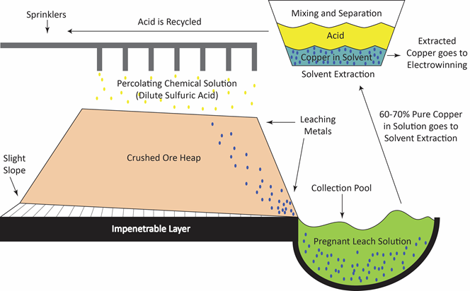
Leaching is one of many solid-fluid separation processes that are carried out in the chemical, mineral and related industries. In fact, it is one of the oldest unit operations in the chemical industries and has been given many names. Leaching and lixiviation both refer to the percolation of the liquid solvent that is used through a fixed bed of solid. If the soluble material is mostly on the surface of its associated in soluble solid, the process of washing off the soluble portion is known as elutriation, or elution.
The rate of leaching can be affected by many physical and chemical phenomena. Mass transfer and equilibrium phenomena obviously play important roles. It is not a simple matter, however, to theoretically predict leaching rates, and quite frequently, experimental data are required to yield the rates. Furthermore, bench-scale data must often be scaled up empirically without attempts at calculating equilibrium data and rate expressions.
 |
Application of leaching
Other names that are encountered in chemical engineering practice include extraction, solid-liquid extraction, infusion, washing and decantation-settling. However, it must be noted that the fundamental principle behind leaching is the removal of a soluble fraction, from an insoluble, permeable solid phase with which it is associated. The soluble fraction may be solid or liquid, and may be held within, chemically combined with, adsorbed upon, or held mechanically in the pore structure of the insoluble material. In the latter case, the separation consists merely of the displacement of one interstitial liquid by another with which it is miscible.
Operation Modes
The leaching process in this project will be carried out in two different operational modes or to be specific, three different operation conditions: use pure solvent, recycled solvent, and pure solvent at elevated temperature. The concentration changes in the various vessels will be measured and the results used to determine rate or “time” constants for the process. The model equations used in describing the system parameters assume that all vessels are “well-stirred”. This is a reasonable assumption for the holding tank and particularly the reboiler, but is less valid for the leaching vessel where significant concentration gradients may arise both within the impregnated particles, and in the solvent itself. The parameters derived from the model must therefore be regarded as empirical approximations.
 |
Pumping Mode
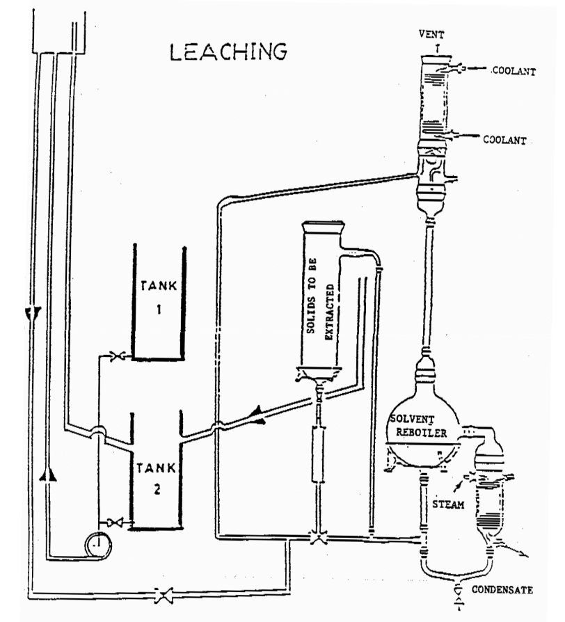
In pumping Mode, extract from the leaching vessel containing a charge of firebrick is impregnated with dye in pumped to a holding tank and back again to the leaching vessel. The dye content of the holding tank increases while that in the leaching vessel steadily diminishes until the two concentration are equal. Another orientation of the pumping mode involves pumping fresh solvent through the leaching vessel which is similar to boiling mode described below with the exception of temperature being different.
Boiling Mode
In boiling Mode, the leaching vessel is contacted with fresh solvent at elevated temperature instead of re-circulated extract. This is accomplished by passing extract from the leaching vessel to a reboiler where solvent is boiled, condensed/cool and returned to the leaching tank. During this operation, concentration in the leaching vessel steadily diminishes until all solute has been transferred to the reboiler.
Equations and Derivations
The model equations used in describing the system parameters assume that all vessels are “wellstirred”. This is a reasonable assumption for the holding tank and particularly the reboiler, but is less valid for the leaching vessel where significant concentration gradients may arise both within the impregnated particles, and in the solvent itself. The parameters derived from the model must therefore be regarded as empirical approximations, which are nevertheless useful in obtaining a first estimate of the system dynamics.
The model equations are obtained from simple unsteady solute mass balances around the vessels in question for the two modes used:
Boiling Mode
- Leaching Vessel
- Reboiler Vessel
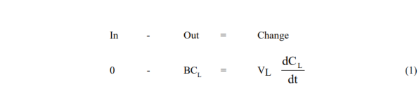

Solutions are obtained by first integrating (1), and substituting the result in (2)

and

Where V = fluid volume, C = concentration, C1 = initial dye concentration, B = solvent flow rate, and subscripts L and B refer to the leaching vessel and reboiler respectively.
Equation 4 has the correct properties that when t is zero CB is zero and when t is large CB becomes C1(VL/VB) and all the dye is in the boiler.
In practice, there will be a diffusive resistance to transfer in the extraction vessel which will slow down the process; thus the equation may take the form,

where K is now an empirical rate constant (time-1). The largest that K can be is (B/VL) but it will usually be smaller and will include the diffusive resistance (1/KD) in series:

KD should be related to the pore diameter and diffusivity. When KD is large (diffusion is fast) the equation reduces to its original form.
We can also rewrite equation 5 in the form,

which shows that a semi-log plot of (1 – CBVB/VLC1) v.s time should be approximately straight with a slope K. By calculating K from measured data for CB = f(t), and known values of VL, VB, C1, we can deduce KD and thus describe approximately the behaviour of the leaching process.
Pumping Mode
- Leaching Vessel
- Reboiler Vessel
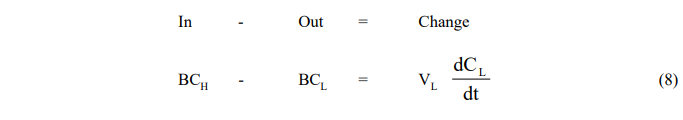
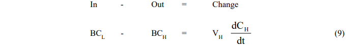
where the subscript H refers to conditions in the holding tank.
Since the equations are coupled, they cannot be integrated separately and are solved instead by Laplace transformation. One obtains,
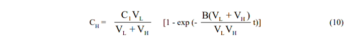
and,
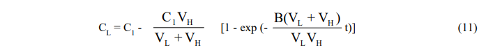
Here again, the exponential factor B(VL + VH)/VLVH may be replaced by the empirical time constant K to reflect the diffusional resistance in the leaching vessel and the resulting equation put in the form (7) for plotting purposes.