Equipment Description
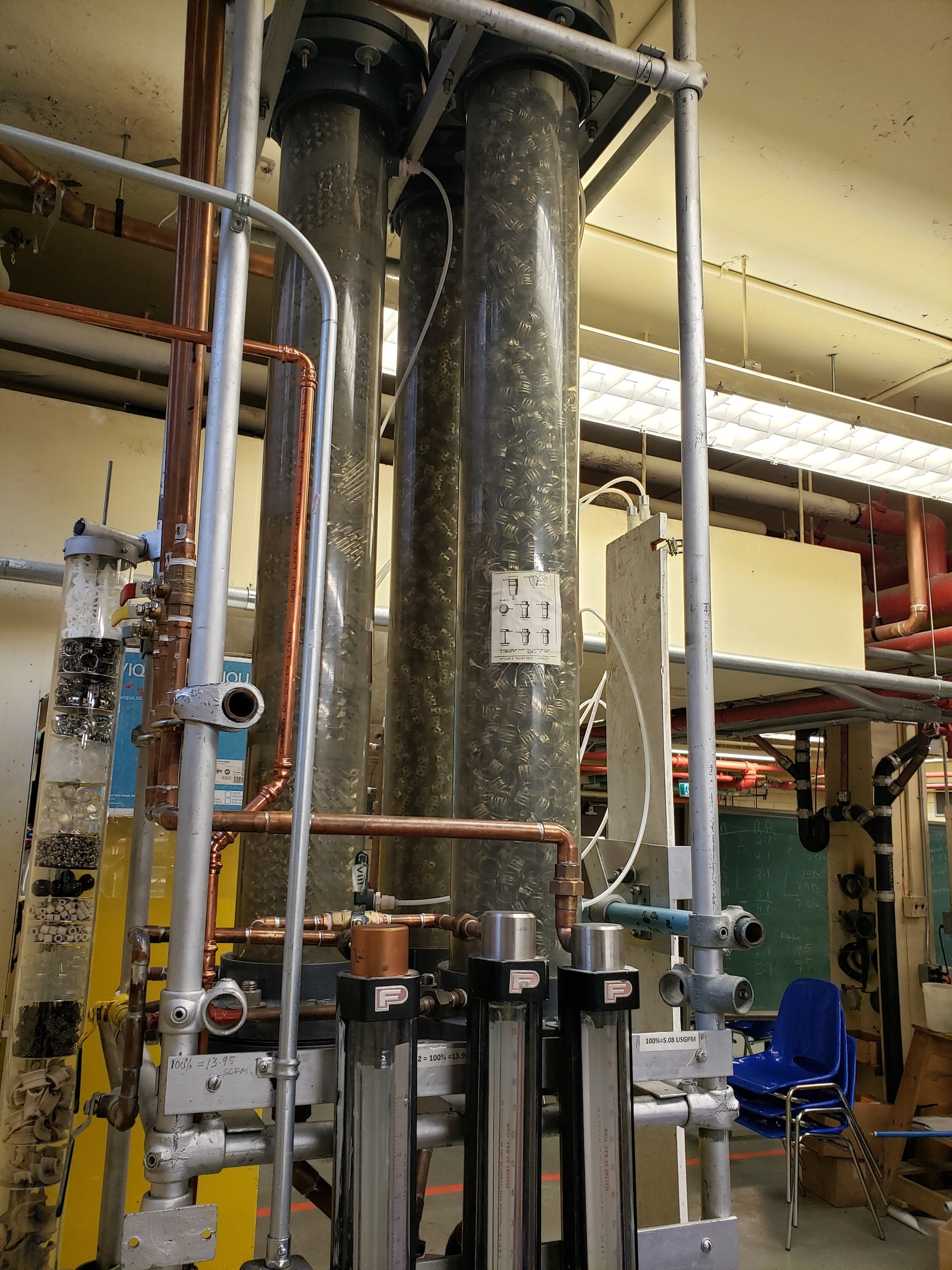
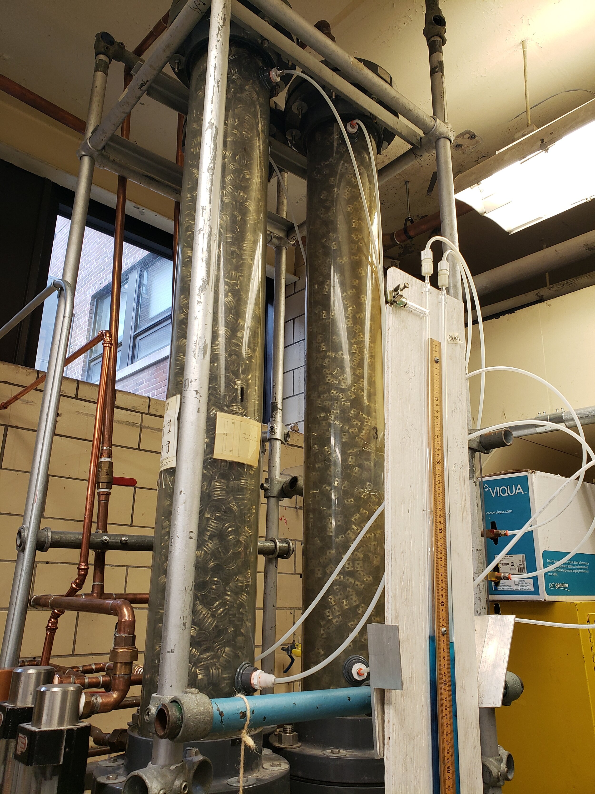
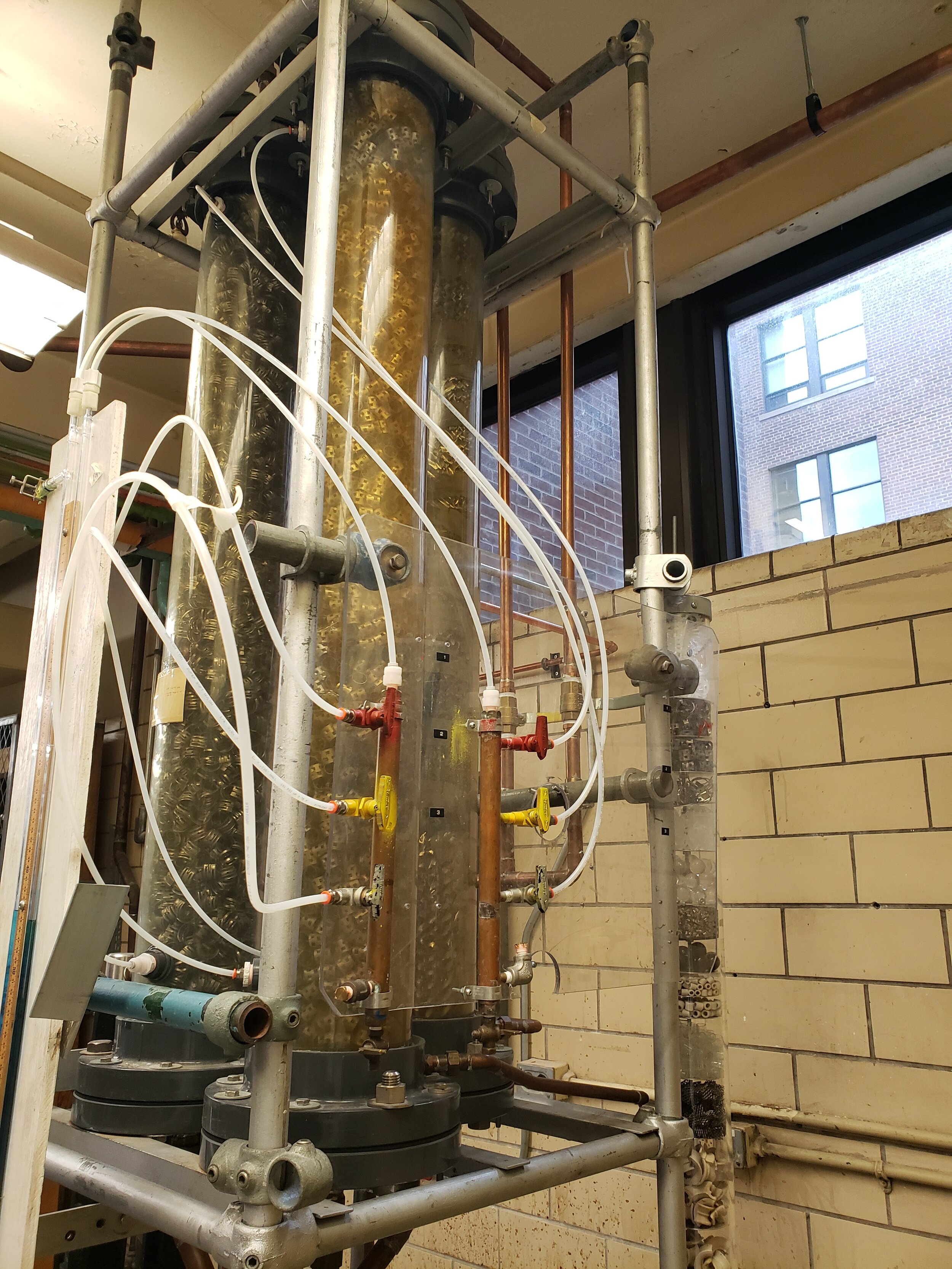
The packed columns consists of a centrifugal pump, three packed columns (nutter ring, structured and ballast rings packing), a tank which serve as the receiving and storage tank for the pumping fluid (water), nine valves, an actuator, a U-tube manometer for measuring differential pressure, and three flow meters for air and water flow rate measurements.
Background & Theory
To review concepts behind the leaching process, click here.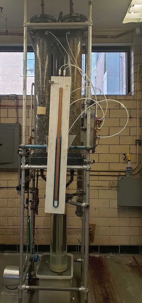
Virtual tour of the operation unit
ZOOM IN AND OUT TO SEE THE CLOSER LOOK OF THE OPERATION UNIT. YOU CAN ALSO SELECT ANY OF THE FOLLOWING CLOSE-UP TOUR TO SEE VALVES AND MEASUREMENT DEVICES ON THE UNIT.
2D P&ID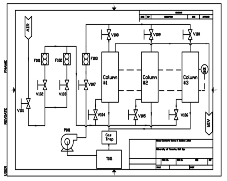
Click the image to download the SOP.
Videos of the Procedure
Gallery
STANDARD OPERATING PROCEDURE
Procedure:
The procedure section will be split into three different sections: A for flow through nutter ring packing; B for flow through structured rings; C for ballast ring packing.
Section A: Flow Through a Nutter Ring Packed Column
Startup Checklist:
-
Bottom Tank (T101) is filled to 75% of the height of the tank
-
Pump is off
-
Valves V101 – V110 are closed
-
Pressure taps for each column is closed
-
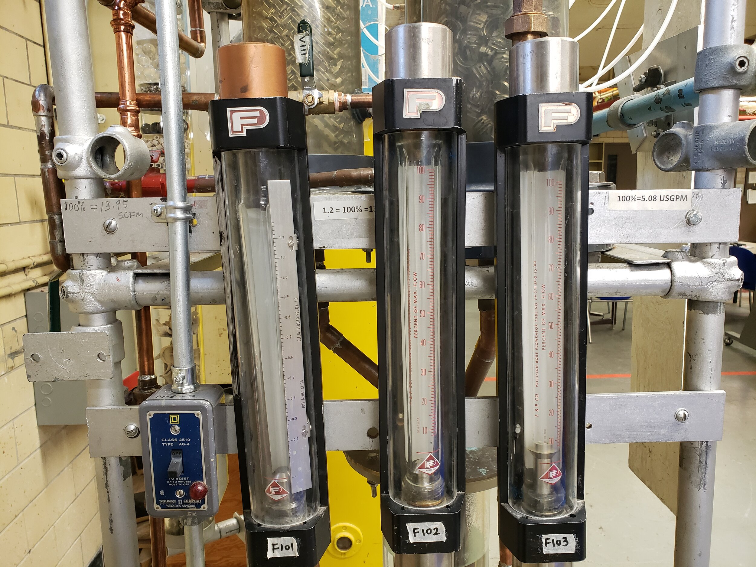
Flowmeters, F101, F102, F103, are all reading zero flow
-
Height different in the manometer is equal to zero
Operating Guide:
-
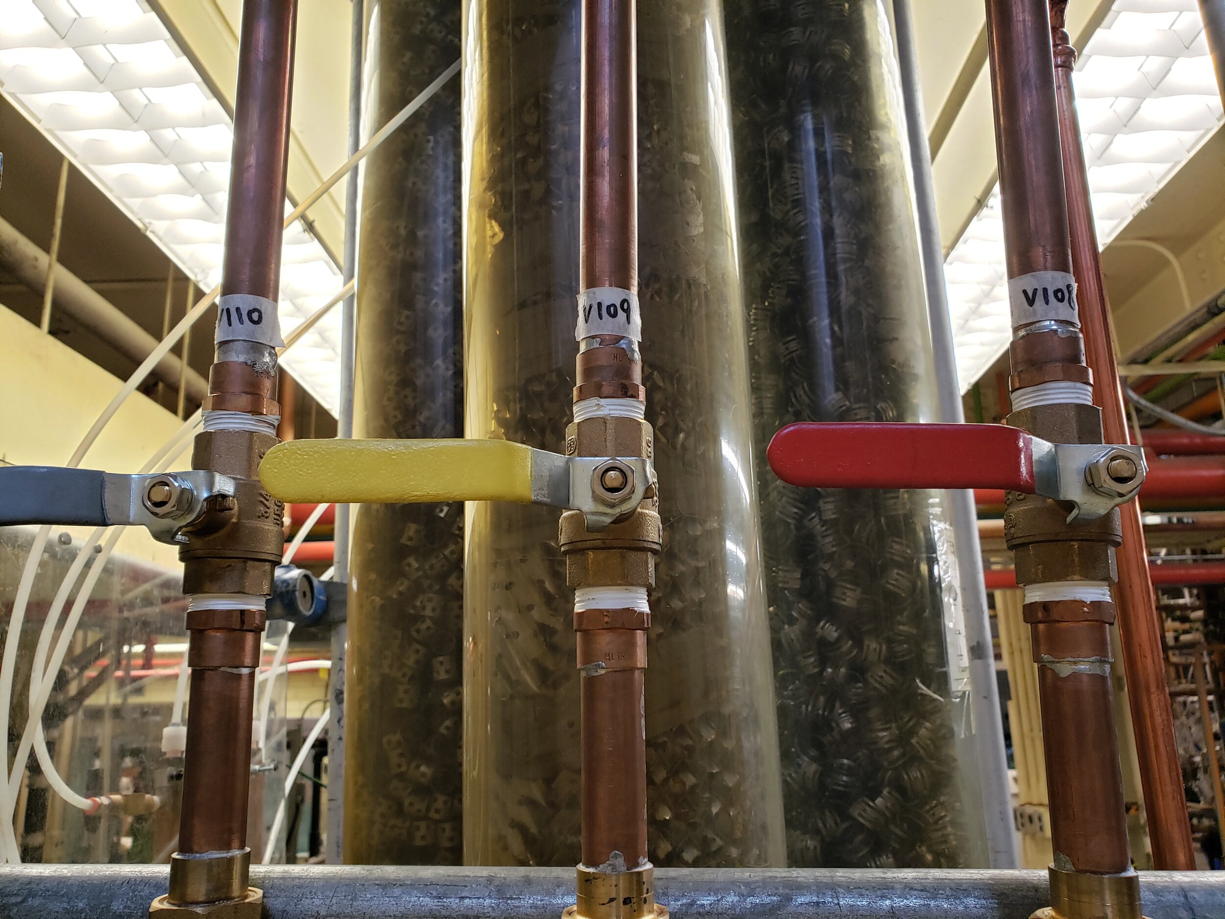
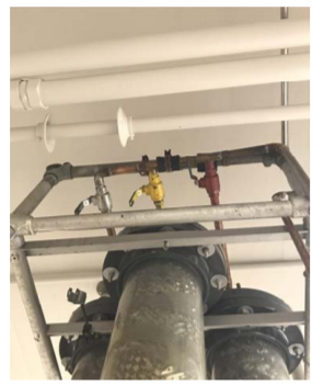
Open red valves V104 and V108 – use an actuator to open V108
 Valves V110, V109, V108
2. Open the red pressure taps
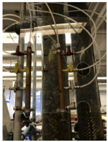 Pressure taps
3. Turn on the main air supply valve, V101 (Shown below)
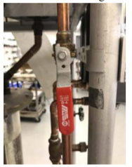 Main Air Supply Valve, V101
4. Flush column 1 with air for 1 minute using air only valve V102 shown in the figure below. (Note: DO NOT turn on the water pump.)
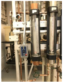 V102 and V103
5. Adjust air flowrate by manipulating air valve V102 (left) and V103 (right)
6. Do a few runs using different air flow rates (no water flow). For each run measure the flowrate using F103 and the pressure drop across the column using the U-tube manometer PG101.
7. Repeat step 6 for different water flow rates:
-
Turn on the pump
-
Adjust the water flowrate using valve V107 (figure 10) and measure the corresponding flowrate from F103
-
Allow the column to reach steady state before recording the pressure drop. Check the flow rates periodically to ensure they are constant
-
Record the conditions (flowrates and pressures) for which flooding occurs in each column

Section B: Flow through Structured Ring Packed Column
Operating Guide:
1. Close all valves and manometer pressure taps
2. Open valves V105 and V109 (both yellow)
3. Open the yellow pressure taps
4. Repeat steps A3-7
Section C: Flow Through Ballast Ring Packed Column
Operating Guide:
1. Close all valves and manometer pressure taps
2. Open valves V106 and V110 (both grey)
3. Open the grey pressure taps
4. Repeat steps A3-7
Shutdown Procedure:
-
Close valve V107 to stop water from flowing into the packed column. Ensure flow meter F103 reads zero.

2. Turn off pump by turning the switch ‘off’ position (figure 9)
3. Reduce the airflow to dry the column for 15 minutes after the experimental run
4. After 15 minutes:
a. Close air valve V102
b. Close main air supply valve V101
5. Close the pressure taps
6. Close all other valves
Shutdown Checklist:
-
Bottom tank is filled with water to ¾ of the tank height
-
Switch for Pump is at ‘off’ position
-
Main air valve V101 is at ‘off’ position
-
Water valve V107 is at ‘off’ position
-
Pressure taps for the three columns are closed
-
Column pathway valves (Grey, red and yellow) V104, V105, V106, V108, V109 and V110 are closed
-
Flow meters, F101, F102 and F103 read zero
-
U-Tube manometer reading is steady