Equipment Description
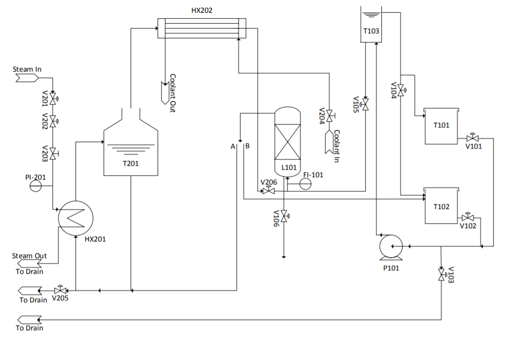
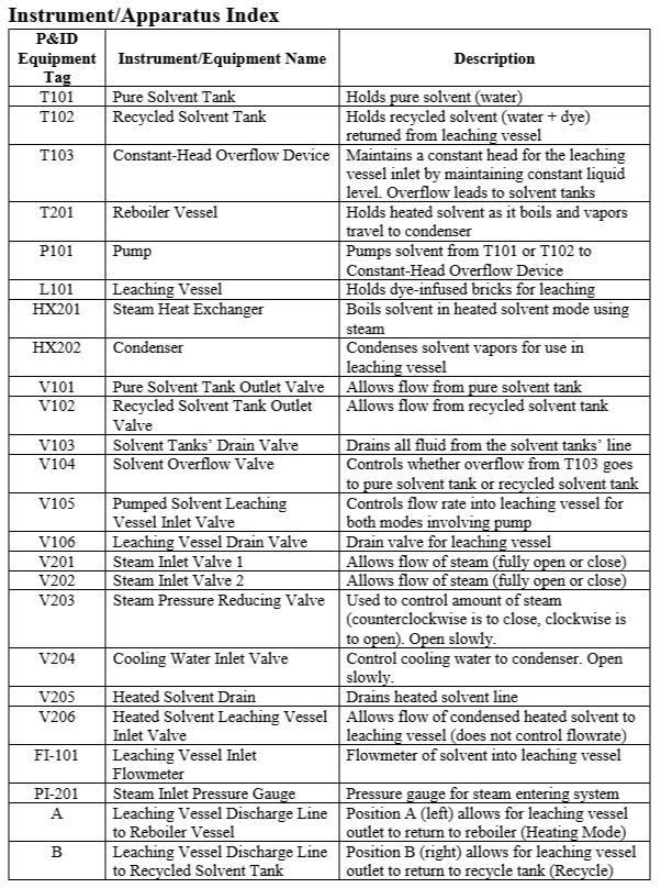
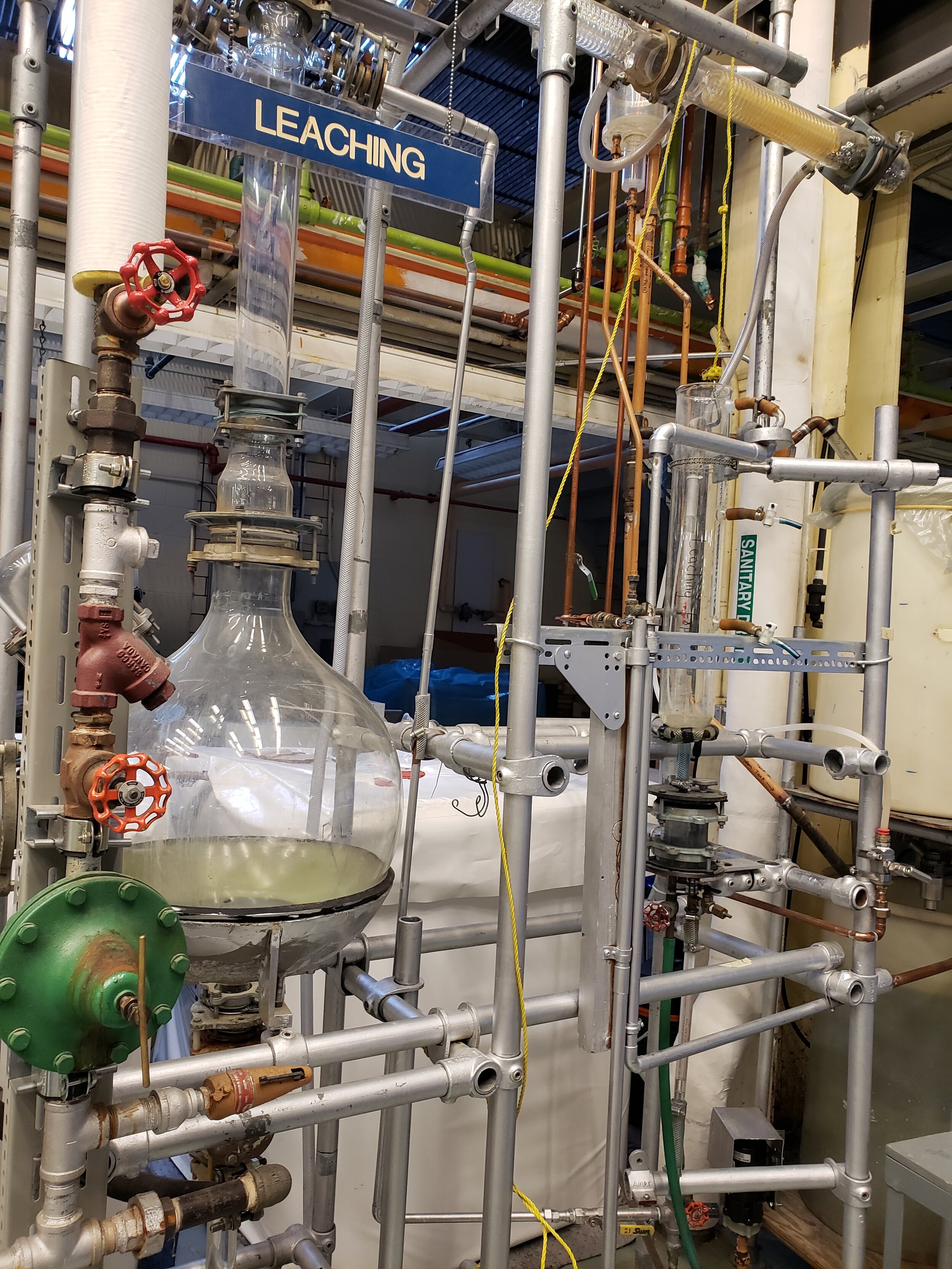
The leaching unit in our lab is a one-stage leaching vessel. In orientation B, all solvent coming out of the tank flows to the recycled solvent tank. There is only one leaching tank (L101) which holds the dye-infused bricks. There are two main holding tanks: pure solvent tank (T101), recycled solvent tank (T102). Depending on the operation, the solvent (water) will flow from the pure solvent tank through the leaching vessel and the outflow is sent to the recycled solvent tank. In recycling mode, the feed comes from the recycled tank instead. There is another tank known as the “constant-head overflow tank”. This tank maintains a constant level in the leaching vessel, which provides a constant head for the feed. Pump, P101, brings fluid in and out of the leaching vessel.
In orientation A, the leaching vessel is in “heating mode”. Solvent coming out of the leaching vessel will travel through a heat exchanger which will heat the solvent to its boiling point. The solvent is the flowed to the reboiler vessel, T201. Fluid from this tank then flows through a condenser to condense solvent vapors. Heated solvent from the condenser is then passed through the leaching vessel.
Background & Theory
To review concepts behind the leaching process, click here.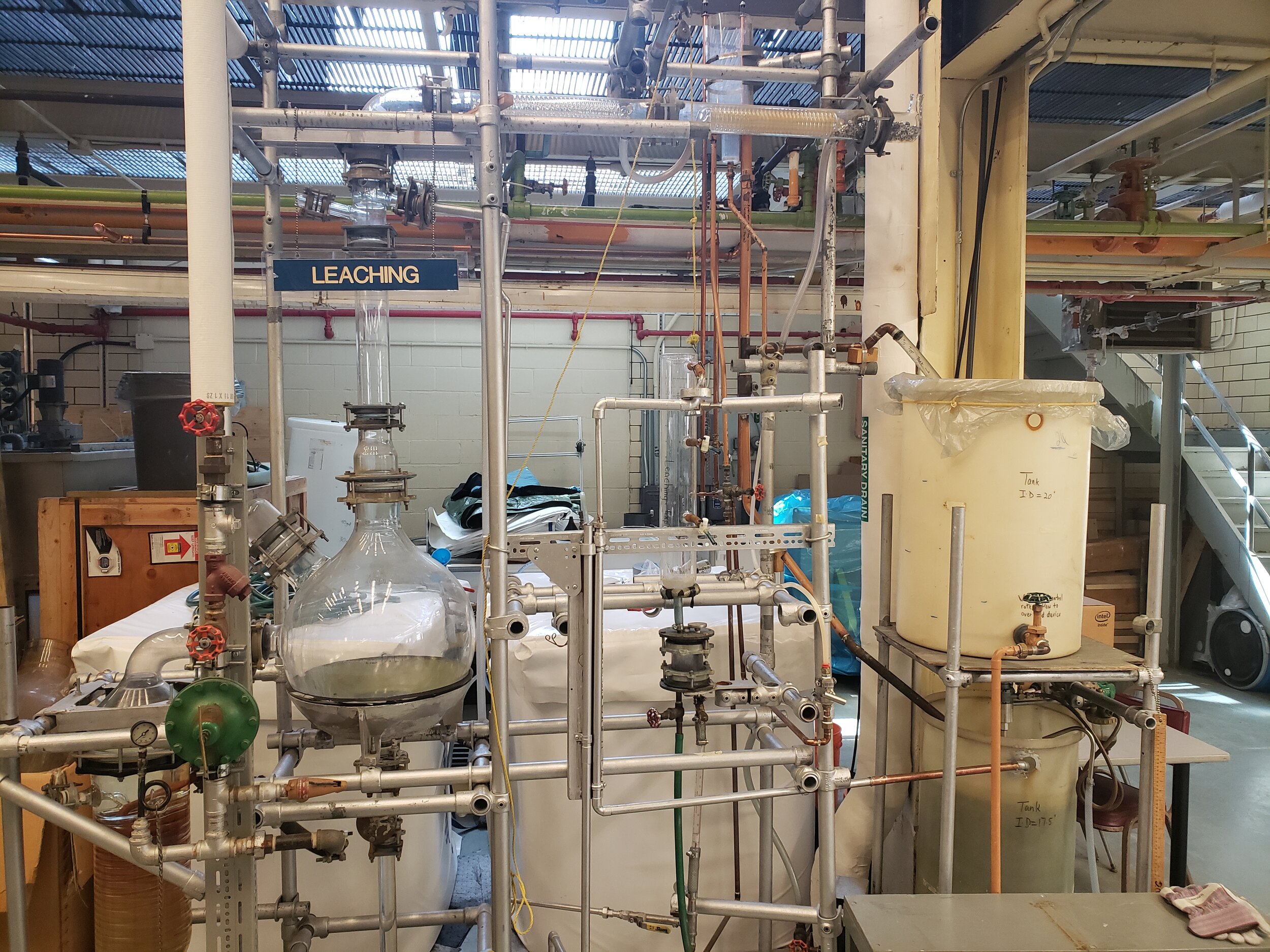
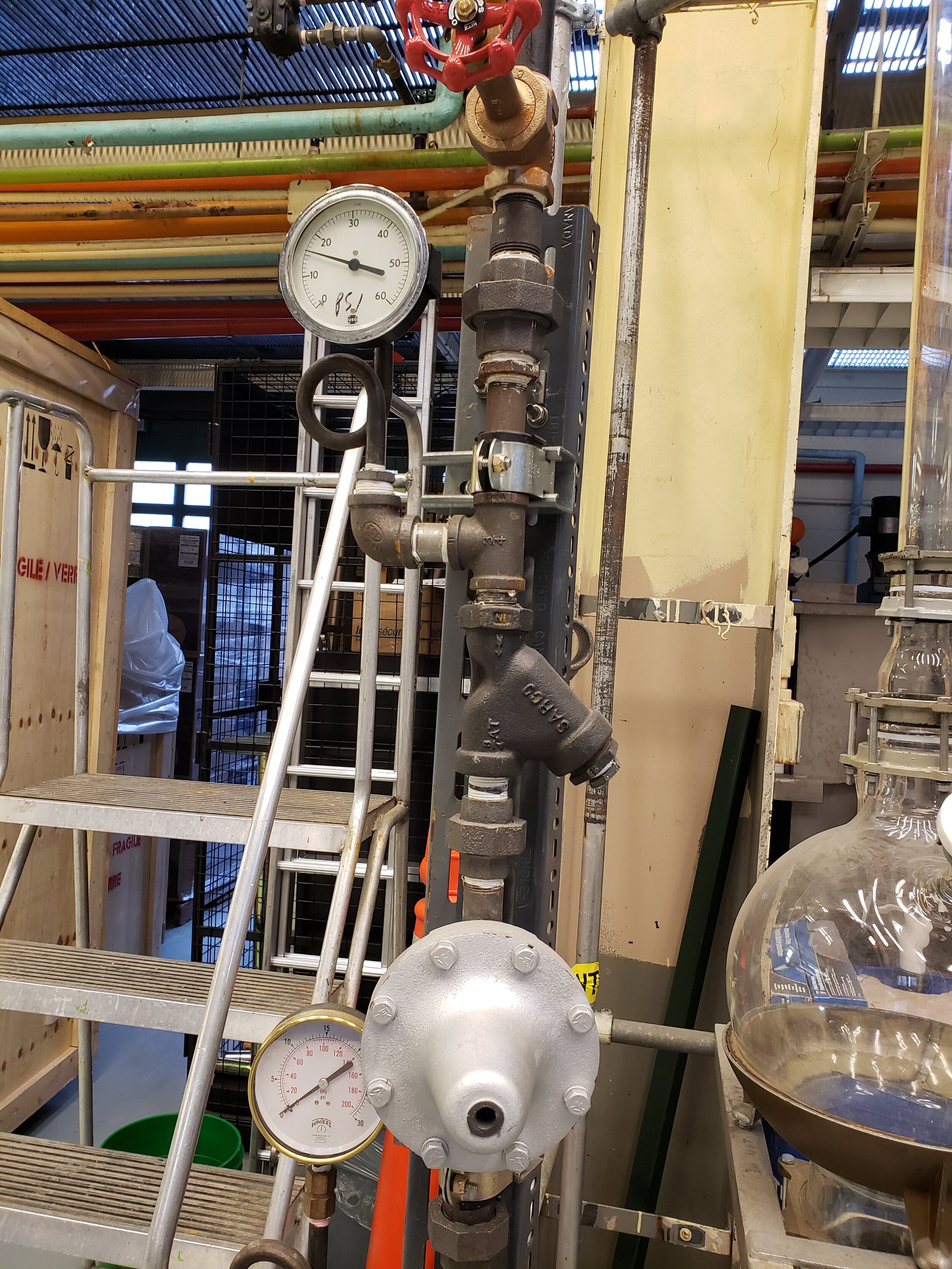
Virtual tour of the operation unit
ZOOM IN AND OUT TO SEE THE CLOSER LOOK OF THE OPERATION UNIT. YOU CAN ALSO SELECT ANY OF THE FOLLOWING CLOSE-UP TOUR TO SEE VALVES AND MEASUREMENT DEVICES ON THE UNIT.
Piping and Instrumentation Diagram
ON A MOBILE DEVICE USE TWO FINGERS TO PAN, AND ONE FINGER TO ROTATE. ON A COMPUTER USE LEFT CLICK TO ROTATE, AND HOLD RIGHT CLICK TO PAN
Click the P&ID image to download the SOP for this experiment.
Gallery
STANDARD OPERATION PROCEDURE
Section B Startup Checklist
1. Pump is off and has power (check circuit panel across from leaching unit–the switch forpump power is green, fourth from the top.)
2. Recycled Solvent Tank Outlet Valve (V102) is closed
3. Solvent Tanks’ Drain Valve (V103) is closed
4. Solvent Overflow Valve (V104) is closed
5. Pumped Solvent Leaching Inlet Valve (V105) is opened
6. Leaching Vessel Drain Valve (V106) is closed
7. Dye-infused bricks are NOT in leaching vessel
Section B: Operation with Pure Solvent
1. When all valves are in the correct position, open V101 to allow flow to the pump
2. Turn on the pump using the powerbar switch to the right of the recycled solvent tank
3. If there are signs of cavitation, turn off pump, close V101 and open drain valve (V103).
When liquid is drained, close V103 and return to step (1)
4. If there is too much flow to constant-head overflow device (i.e. water is overflowing)
reduce water supply by adjusting V101
5. Adjust flowrate of solvent to leaching vessel by adjusting pumped solvent leaching vessel
inlet valve V105
6. When desired steady state is achieved (all flowrates are as desired), open V106 and drain
leaching vessel to the halfway point. (This is to prevent overflow when introducing the
dye-infused firebricks into leaching vessel)
7. Insert mesh basket filled with dye-infused bricks into leaching vessel
Section B Shutdown Checklist
1. Pump is turned off
2. V101 is closed
3. Liquid line is drained with V103
4. Leaching vessel drained with V106
Section C Startup Checklist
1. Pump is off and has power (check circuitpanel across from leaching unit–the switch forpump power is green, fourth from the top.)
2. Pure Solvent Tank Outlet Valve (V101) is closed
3. Solvent Tanks’ Drain Valve (V103) is closed
4. Solvent Overflow Valve (V104) is open
5. Pumped Solvent Leaching Inlet Valve (V105) is opened
6. Leaching Vessel Drain Valve (V106) is closed
7. Leaching Vessel Discharge Line is in position B (right side)
8. Dye-infused bricks are NOT in leaching vessel
Section C: Operation with Recycled Solvent
1. When all valves are in the correct position, open V102 to allow flow to the pump
2. Turn on the pump using the powerbar switch to the right of the recycled solvent tank
3. If there are signs of cavitation, turn off pump, close V102 and open drain valve (V103)
When liquid is drained, close V103 and return to step (1)
4. If there is too much flow to constant-head overflow device (i.e. water is overflowing)
reduce water supply by adjusting V102
5. Adjust flowrate of solvent to leaching vessel by adjusting pumped solvent leaching vessel
inlet valve V105
6. When desired steady state is achieved (all flowrates are as desired), open V106 and drain
leaching vessel to the halfway point. (This is to prevent overflow when introducing the
dye-infused firebricks into leaching vessel)
7. Insert mesh basket filled with dye-infused bricks into leaching vessel
Section C Shutdown Checklist
1. Pump is turned off
2. V102 is closed
3. Liquid line is drained with V103
4. Leaching vessel drained with V106
Section D Startup Checklist
1. Steam inlet valves V201 and V202 are closed
2. Steam Pressure Reducing Valve (V203) is fully closedo NOTE: This type of valve is the opposite to all other valves–clockwise rotationopens the valve, counterclockwise rotation closes the valve
3. Heated Solvent Drain (V205) is closed
4. Heated Solvent Leaching Vessel Inlet Valve (V206) is open
5. Leaching Vessel Discharge Line is in position A (left side)
6. Dye-infused bricks are NOT in leaching vessel
Section D: Operation with Heated Solvent
1. Open steam inlet valve 1 (V201). This can be opened fully
2. Open steam inlet valve 2 (V202). This can be opened fully
3. Slowly open steam pressure reducing valve (V203) by turning clockwise. Do so until
you see flow through the tubes in the steam heat exchanger (HX201).
4. Slowly open cooling water inlet valve (V204) until you see water flow in the condenser at the top of the unit (HX202)
5. From this point, continuing opening the steam pressure reducing valve (V203) slowly (around 2 notches every 30 seconds) until the steam pressure gauge (PI-201) reads 15
psig OR until there is a rolling boil in the reboiler vessel (T-201)
6. Continue to adjust the cooling water flowrate by adjusting V204. If steam is seenexiting the condenser from the right-hand side, the cooling water flowrate is insufficient. Ideally you should see condensate occurring along the left half of the condenser, otherwise the cooling water flowrate may be too high
7. When a desired steady-state is achieved (all flowrates are as desired), open V106 and
drain leaching vessel to the halfway point. (This is to prevent overflow when
introducing the dye-infused firebricks into leaching vessel)
8. Insert mesh basket filled with dye-infused bricks into leaching vessel
Section D Shutdown Checklist
1. V201 is closed first, and after approximately 1 minute, V202 is closed as well
2. V203 can be left open for any residue steam to exit the system. Close after ~5 minutes
3. Leaching vessel is drained using V106
4. Heated Solvent line is drained using V205