Equipment Description
In our lab, we will directly be working with two different heat exchangers: shell & tube, and plate & frame. Other heat exchangers, like the reboiler and condenser of the distillation columns, will be reserved for their respective SOPs to narrow the scope of the discussion.
Our shell & tube heat exchanger has a U-tube orientation for the internals of the exchanger. So although the flow is single-pass, depending on the fluids positions -heating and cooling elements- is in either a co-current or countercurrent arrangement. The heat element, steam, and cooling element, water, flow by simply opening their respective valves. The difference in pressure in the inlet and outlet causes the fluids to flow in and out of the system. Pressure relief valves are present throughout the system to ensure safe operation. When it comes to operating, please ensure you have read the SOP carefully and listen to the TA. This experiment can lead to serious safety hazards if the pressure of the steam valve rises to too high of a value.
The plate & frame heat exchanger is connected to the same system as the shell & tube. To operate this equipment, simply turning some valves and directing the flow of fluids to this exchanger is all you need to do.
Background & Theory
To review concepts, click here.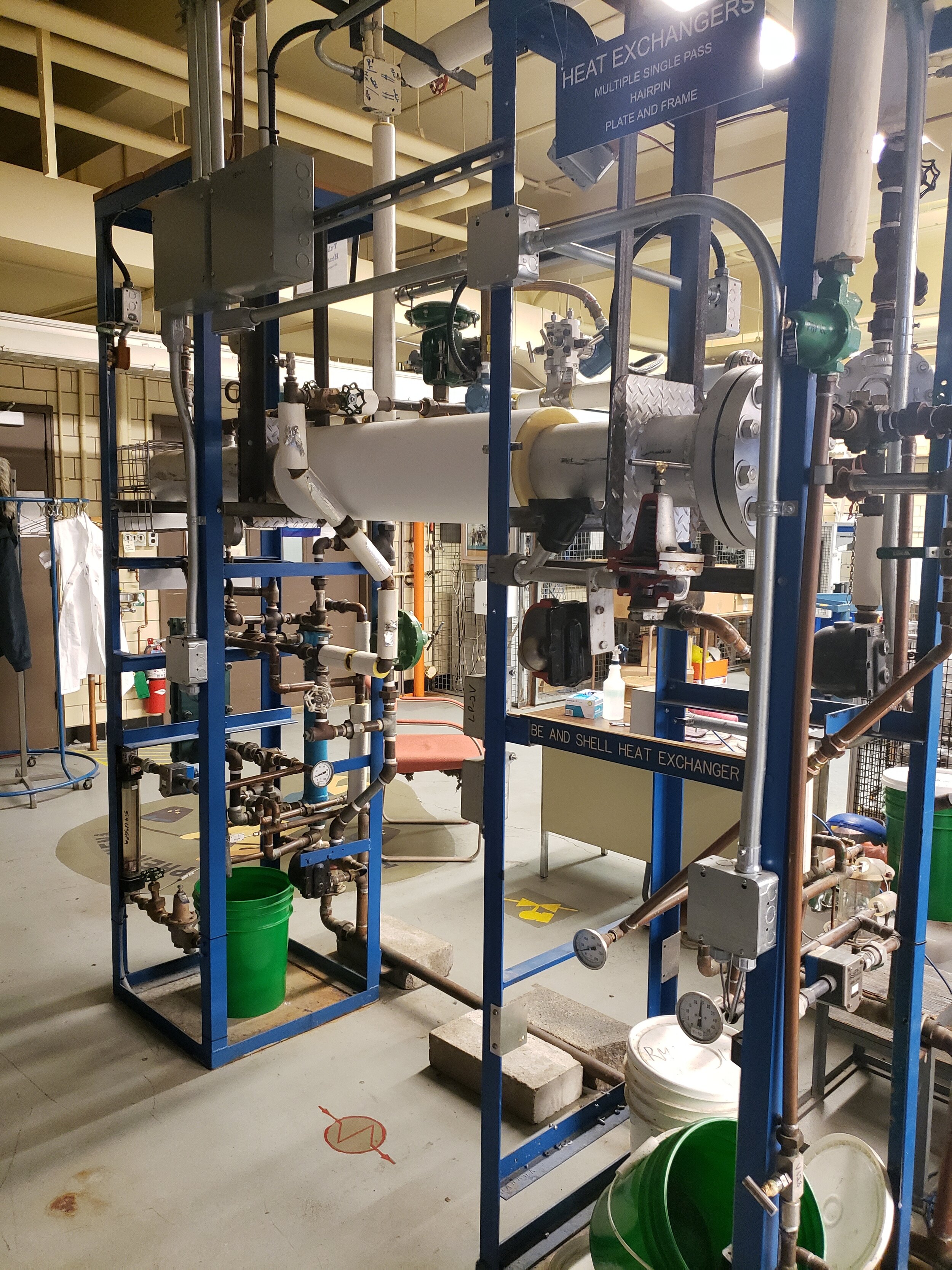
Virtual tour of the operation unit
ZOOM IN AND OUT TO SEE THE CLOSER LOOK OF THE OPERATION UNIT. YOU CAN ALSO SELECT ANY OF THE FOLLOWING CLOSE-UP TOUR TO SEE VALVES AND MEASUREMENT DEVICES ON THE UNIT.
Piping and Instrumentation Diagram
ON A MOBILE DEVICE USE TWO FINGERS TO PAN, AND ONE FINGER TO ROTATE. ON A COMPUTER USE LEFT CLICK TO ROTATE, AND HOLD RIGHT CLICK TO PAN
2D P&ID and SOP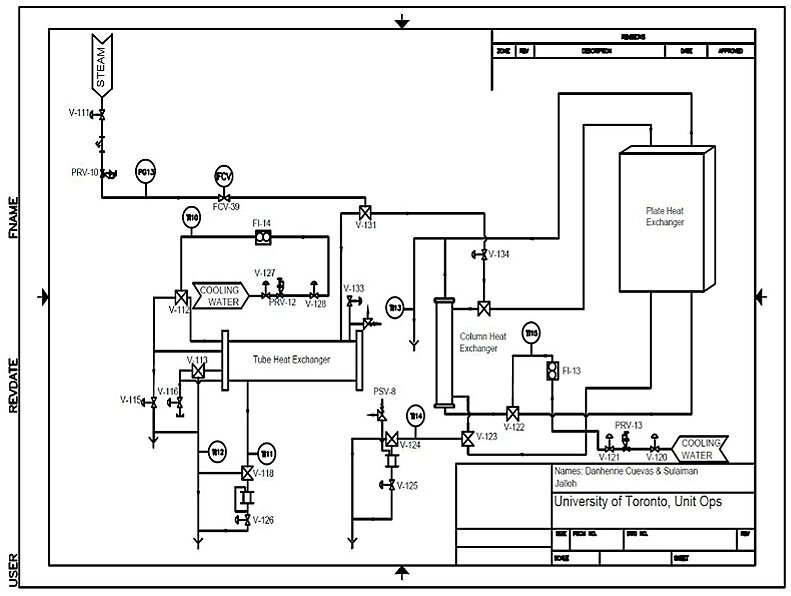
Click the image to download the SOP. The key for the P&ID can be found in the SOP.
Standard Operation Procedure
Startup Checklist
-
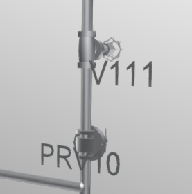
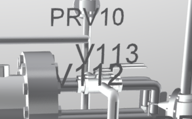
Steam valves V-111, PRV-10 are closed
-
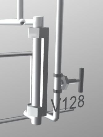
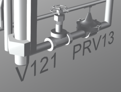
Cold water valves V-121 and V-128 are closed
-
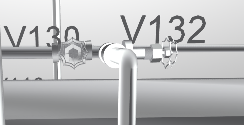
Steam bypass valves V-114, V130, V132 and V-134 are closed
-
Delta-V is displaying main menu
-
Digital readout of FCV-39 is at 0 psi
-
The pressure gauge (PG 13) reading on the steamline is registering zero
-
FI-13, FI-14 show 0% flow
-
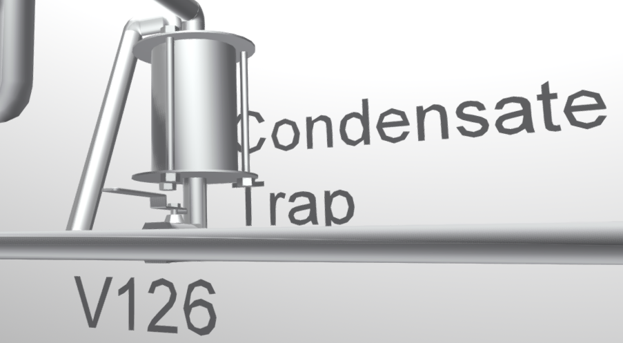
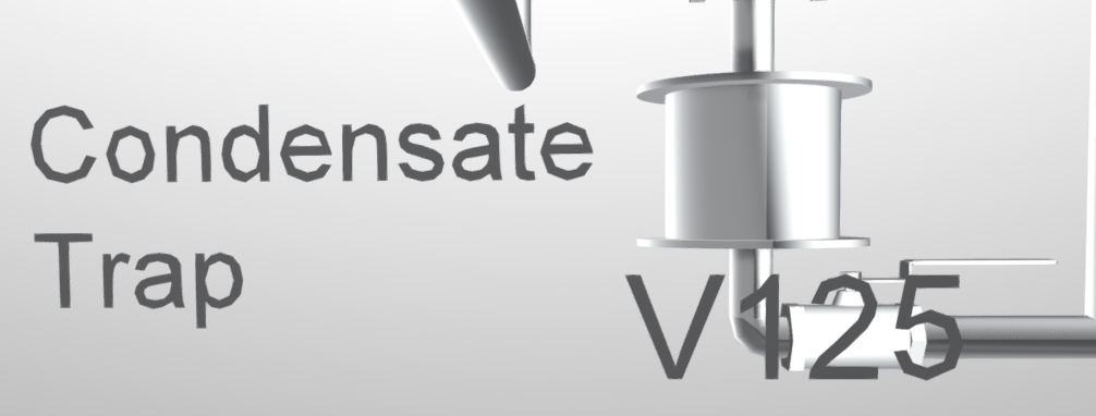
Check both condensate traps and ensure 0% liquid level, if not, open valve V-125 or V-126 for drainage
Part I. Tube and Shell Hair-Pin Heat Exchanger

Section A: Start up Procedure
-
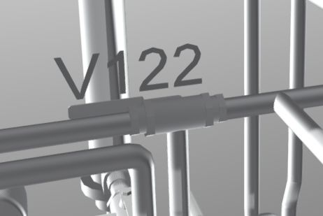
Position three-way valve V-122 to allow cold water to flow through the Single Pass HX
-
Slowly open V-121 to introduce cooling water into the system
• Adjust flow seen in FI-13 to 80%
-
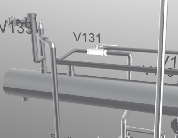
Configure valve V-131 for the desired steam pathway for Single Pass HX
• This valve is very difficult to turn, use a stool when adjusting for better leverage
-
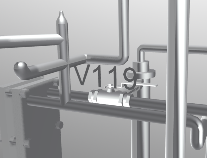
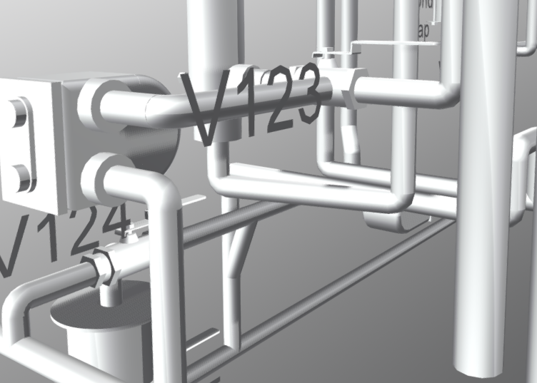
Configure three-way valve V-119 to allow steam into Single Pass HX and three-way valve V-123 to allow steam out of Single Pass HX. (Note, V-123 only turns counter-clockwise)
-
Configure three-way valve V-124 to allow condensate to pass through trap and ensure valve V-125 is open.
-
Open bypass valve V-132 to prepare system for condensate flush
-
Verify steam pathway by following the piping. Ask a TA to double check the valves is there is any chance you are not sure.
-
Open steam pressure reducing valve PRV-10 by one full turn (clockwise)
-
Turn on steam VERY SLOWLY to purge condensate using valve V-111. If any knocking noise is heard inside the pipes, STOP turning the valve, you may even want to reduce pressure by turning the valve back a half turn counter-clockwise. This knocking sound is STEAM HAMMERING which can destroy valves and pipes.
Caution: Use insulated gloves.
-
Use PRV-10 to VERY SLOWLY adjust steam pressure on PG-13. Caution: Use insulated gloves. Do not exceed 5psig (PG-13) while flushing out condensate
While condensate is flushing, proceed to start up Delta-V
Section B: DELTA-V
-
Click on “CHE 305 Heat Exchanger(s)” at the main screen of the computer.
-
On the right hand side, there steps for running the heat exchanger. First click “Start” then proceed to “Name & Mode Entry”.
-
Type in Date, TA name, Course code, student name and email then click “OK”.
-
Click on “Pres, Temp, Flw Settings” and the Faceplate will appear. Then click on “OK”.
-
Click on “Manual Start-up” and check off steps for one heat exchanger investigated.
-
This step is to verify you have properly followed the Part A HX setup
-
-
Once you have checked off Step 13 (or 12 for Tube HX), you can initiate flow control by going back to the DeltaV P&ID display (“Go back” button) and selecting FCV-39
-
Increase flow with FCV-39 by increments no greater than 20% at a time by clicking the box (See below) and inputting a value. Do not go past 60% at this point in time.
-
Once FCV-39 is opened, close bypass valve V-132 (If using Tube HX, close V-130). All steam flow through system is now controlled using FCV-39 on Delta-V, don’t forget to complete the checklist
-
-
Click on “Start Collection”. If you cannot click this button, you have not finished the checklist
-
Once the FCV-39 is open and bypass is closed, re-adjust the pressure using the PRV-10 and examine the pressure gauge PG-13. It should not exceed 15psig
-
You can now adjust the flow through FCV-39 and examine the effect it has on the temperature of the condensate and cooling water flowing out of the HX. This graph can be seen by clicking the appropriate button for the HX being examined (See below)
Section C: Data Collection for Single Pass and Plate HX
-
The following recordings are taken from the physical gauges on the HX once the system has reached steady state. Observe associated graph to determine steady state.
-
Record the inlet temperature of cold water stream from TI-15.
-
Record the outlet temperature of cold water from TI-13.
-
Record the outlet temperature of the steam line from TI-14.
-
Record the steam pressure using PG-13.
-
Measure and record from indicated instruments shown in Figure 20 to compare readings from apparatus and Delta V software.
-
For each HX run measure the condensate flow rate by recording the time it takes to reach the mark on the glass (desired level).
-
This is done by closing valve V-125 to allow condensate to build up in trap
-
The volume up to the mark is 250mL
-
Section D: Shutdown Procedure
-
Before proceeding to the next HX, you must shut down the system so the valves can be adjusted safely
-
Click “Stop Data Collection”
-
Close V-111 and back off PRV-10 Use insulated safety gloves.
-
Set the valve position of FCV-39 using the delta V program to 0%
-
Decrease setting by maximum 20% intervals
-
-
Click “Manual Shutdown and verify steps shown on the checklist and click “OK” to shutdown program
-
Exit program to go back to the main screen.
-
-
For Single Pass and Plate HX, reduce valve V-121 to 15% flow indicated from FI-13
-
For Tube and Shell HX, reduce valve V-128 to 15% flow indicated by FI-14
-
Ensure liquid is drained in condensate trap
Part II. Plate Heat Exchanger
-
Modify valve pathway for Plate heat exchanger.
-
Valve V-122 should be turned 90° Clockwise (CW) to direct cooling water to plate HX
-
Slowly open Valve V-121 and adjust until flow in FI-13 reaches 80%
-
Do not change V-131, this pathway supplies steam to both single pass and plate
-
Valve V-119 should be turned 90° CW to direct steam into to plate HX
-
Valve V-123 should be turned 180° Counter-clockwise (CCW) to direct steam out of plate HX
-
Do not change V-124, this directs condensate through trap
-
-
Repeat steps Part I A Steps 6-11 to start up steam
-
Restart Delta-V by following Part I B
-
Repeat steps Part I C for recording data and determining condensate flow
-
Repeat steps Part I D to shutdown system
Part III. Tube and Shell Heat Exchanger
Section A: Start up Procedure
-
Adjust three-way valves V-112 and V-113 to allow cooling water (CW) to flow through both pairs of tubes of the Tube and Shell HX.
-
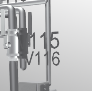
Ensure both drain valves V-115 and V-116 are in the closed position.
-
Open CW valve V-128 and use PRV-12 to adjust flow to 80% as seen in FI-14 .
-
Before adjusting steam valves, ensure PG-13 reads 0psig.
-
Turn three-way valve V-131 90° CCW to change source pathway of steam from Plate and Single Pass HXs toward Tube and Shell HX
-
This valve is very difficult to turn, use a stool when adjusting for better leverage.
-
-
Ensure valve V-126 is open and verify that there is no condensate in the trap.
-
Adjust “three-way valve” V-118 to ensure condensate will pass through trap.
-
Verify PG-14 reads 0psig before opening bypass valve V-130.
-
Follow Part I A steps 7-11 to introduce steam into the system.
Section B: Delta-V
-
Follow Part I B for Delta-V startup.
Section C: Data Collection for Tube and Shell
-
The following recordings are taken from the physical gauges on the HX once the system has reached steady state. Observe associated graph to determine steady state.
-
Record the inlet temperature of cold water stream from TI-10.
-
Record the outlet temperature of cold water from TI-12.
-
Record the outlet temperature of the steam line from TI-11.
-
Measure and record the steam pressure using PG-13.
-
Measure and record from indicated instruments shown in Figure 26 to compare readings from apparatus and Delta V software.
-
Measure the condensate flow rate by recording the time it takes to reach the mark on the glass (desired level).
-
This is done by closing valve V-126 to allow condensate to build up in trap.
-
Section D: Shutdown procedure
-
Follow Part I D for shutdown procedure
Shut Down Checklist
-
All valves are closed: V111, V112, V113, V115, V116, V118, V122, V123, V124, V125, V126, V127, V128, V129, V130, V131, V133 and V134
-
Delta-V system is back on main menu
-
There is no condensate in either of the traps
-
PG13 reads zero psig
-
Let the cool water line run to cool down the system