Equipment Description
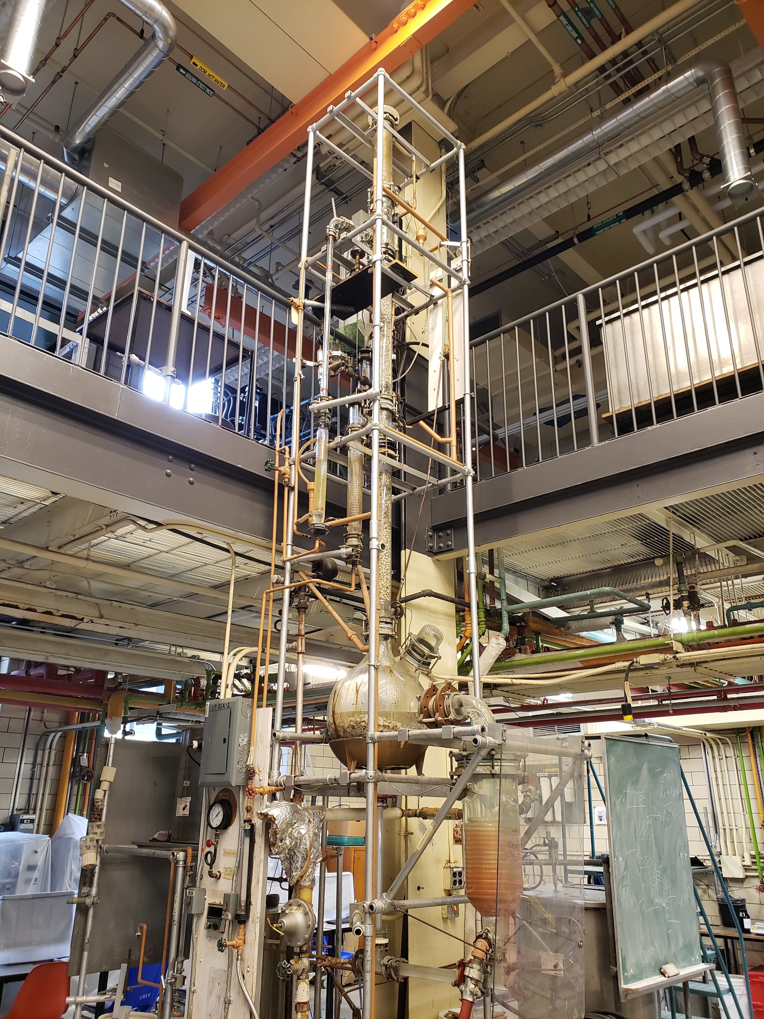
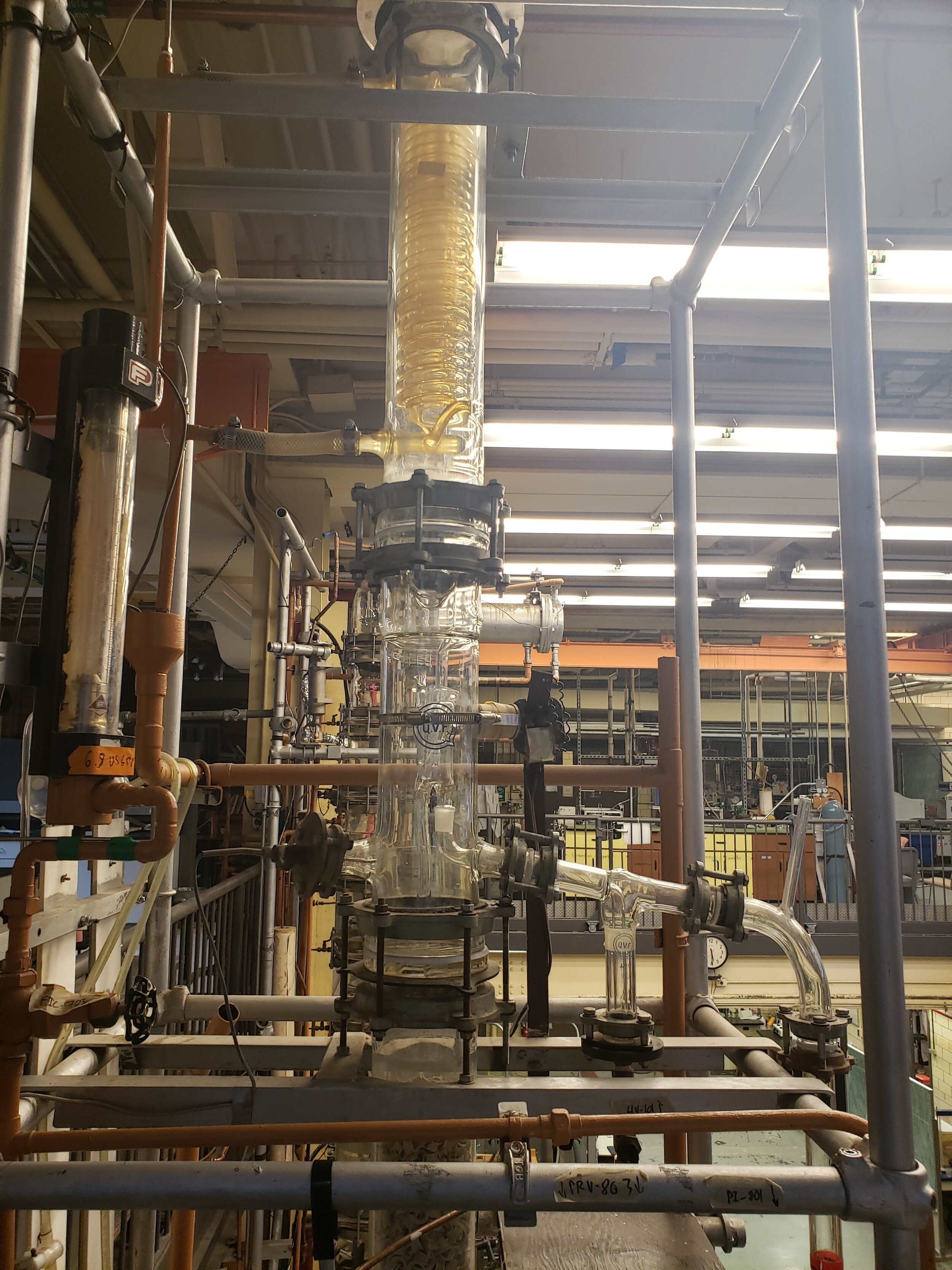
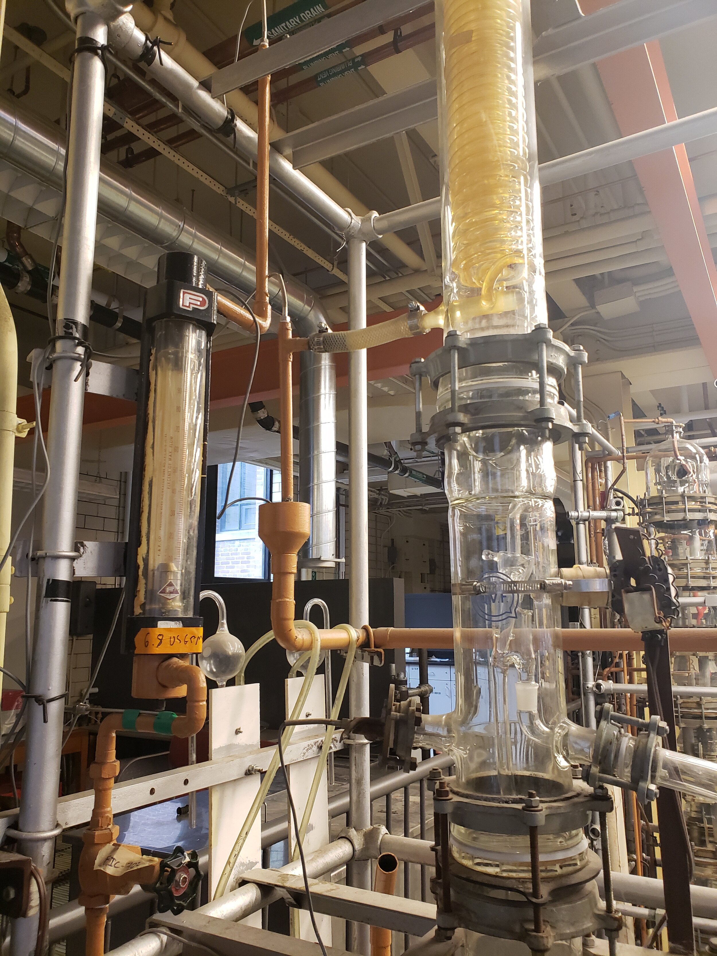
The packed column stands at a height of 20ft and a diameter of 10cm. A pump is used to feed the streams into the column and there are pumps at the condenser and reboiler (to overcome head loss). We assume that the condenser is a total condenser and that the reboiler is total reboiler. The feed is fed at halfway through the packing height. The feed tank can be found on the bottom floor behind the column – specifically, behind where you collect bottom samples. The bottom and distillate tanks are found beside feed tank to the left.
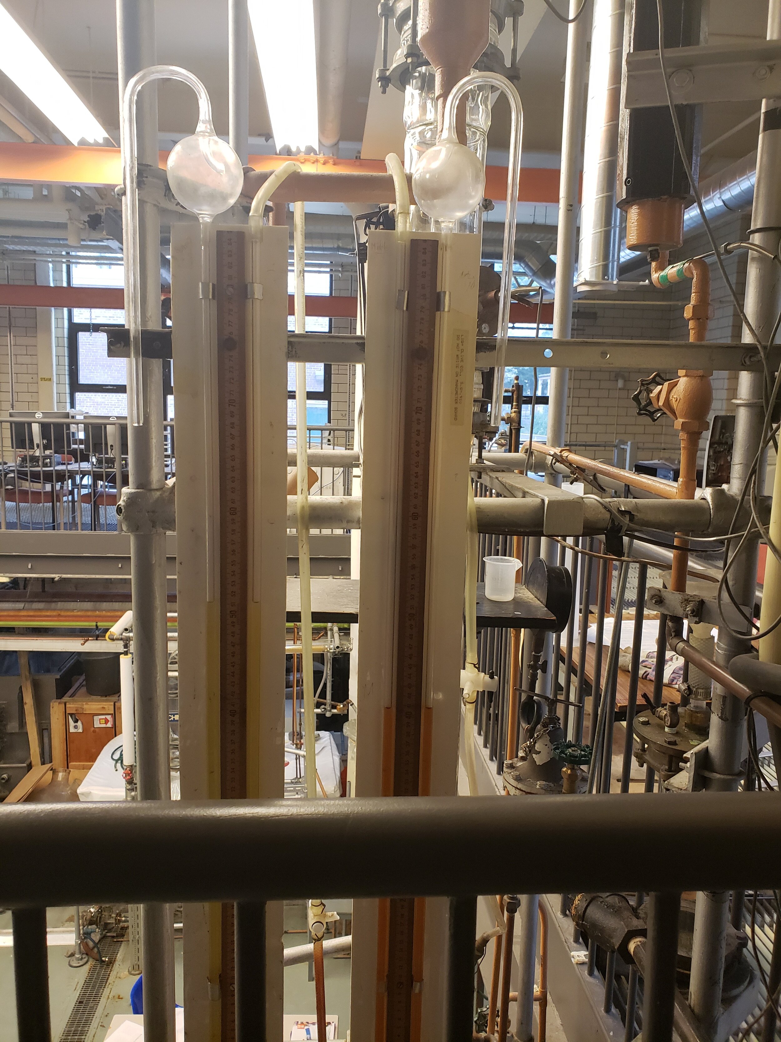
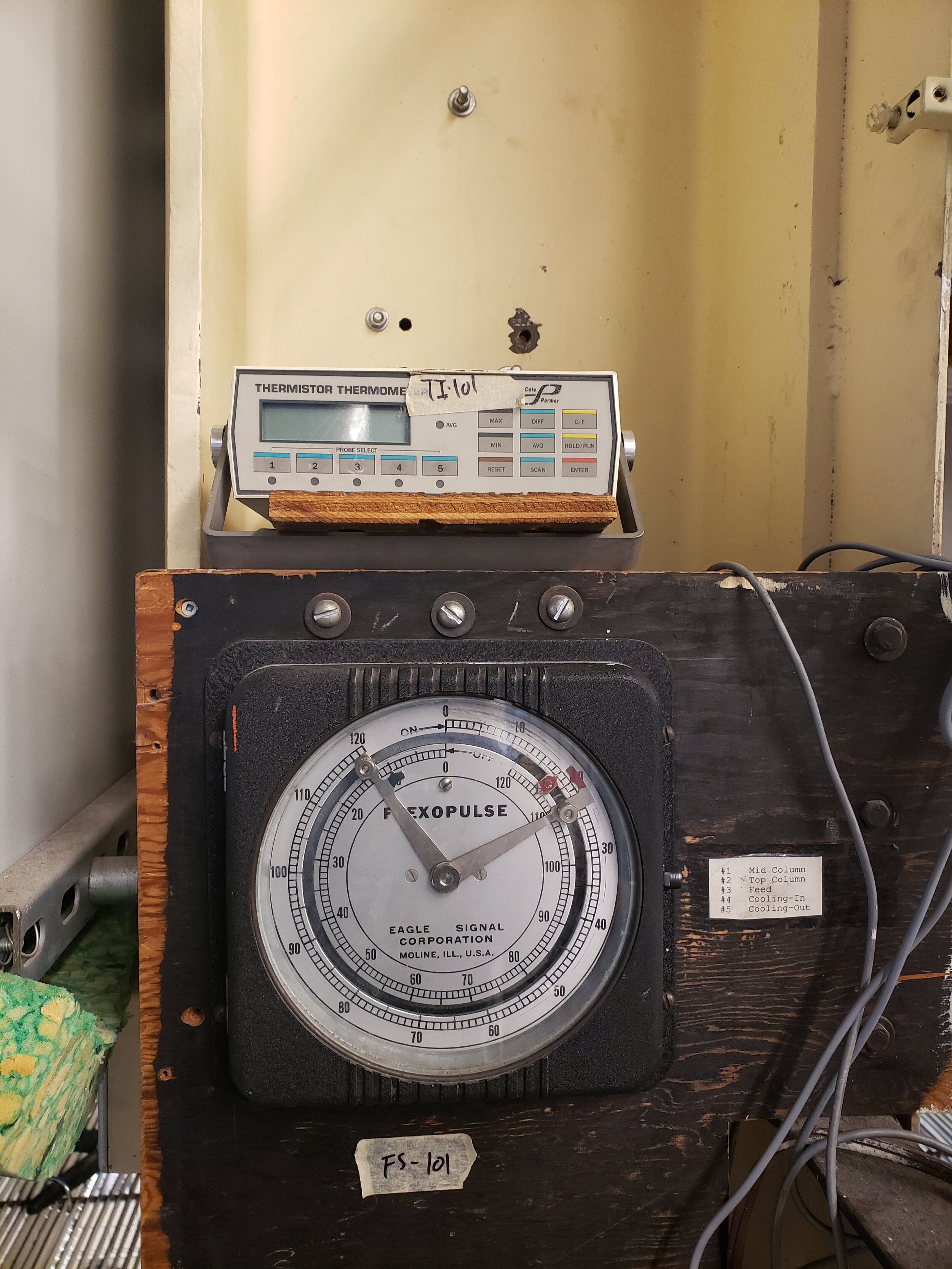
The temperatures in the column are measured by sensors inside the column. The output can be found at the top of the column. The reflux ratio can be changed using equipment above – refer to the SOP or ask the TA for guidelines on its operation. The packing used in our column are 1.25 nominal size (1/2 inch) Intalox saddles with a packing height of 1.72m. Measuring the temperature of different
Background & Theory
To review concepts behind the leaching process, click here.
Virtual tour of the operation unit
ZOOM IN AND OUT TO SEE THE CLOSER LOOK OF THE OPERATION UNIT. YOU CAN ALSO SELECT ANY OF THE FOLLOWING CLOSE-UP TOUR TO SEE VALVES AND MEASUREMENT DEVICES ON THE UNIT.
Piping and Instrumentation Diagram
ON A MOBILE DEVICE USE TWO FINGERS TO PAN, AND ONE FINGER TO ROTATE. ON A COMPUTER USE LEFT CLICK TO ROTATE, AND HOLD RIGHT CLICK TO PAN
2D P&ID and SOP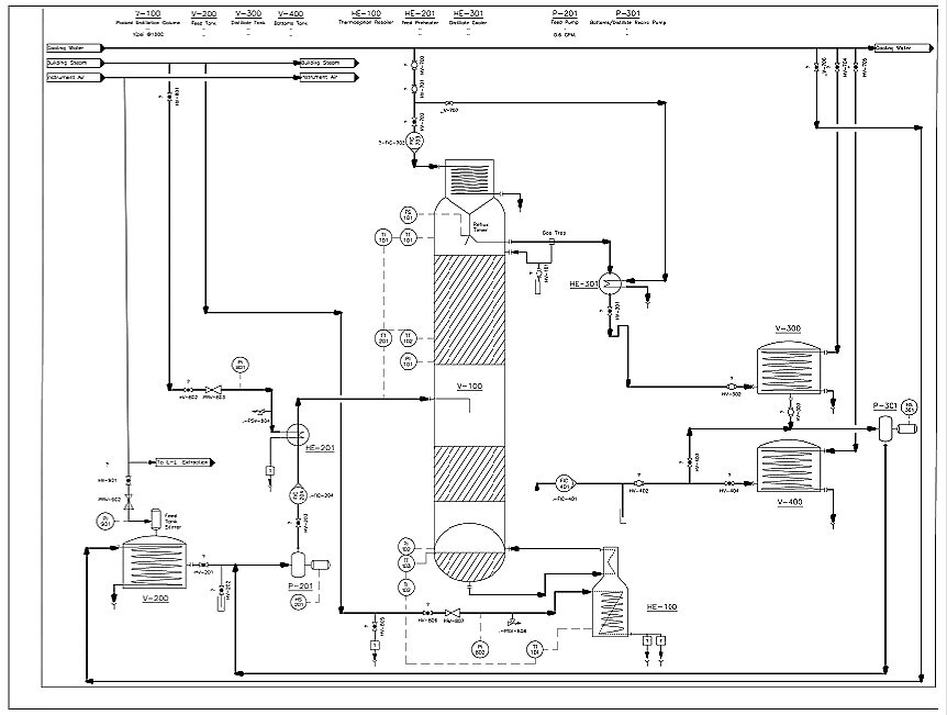
Click the image to download the SOP. The key for the P&ID can be seen in the SOP.
Gallery
STANDARD OPERATION PROCEDURE
3. Introduce cooling water to the condenser.
-
Open HV-700 half way (~45°).
-
Slightly open valve HV-701 (~15°).
-
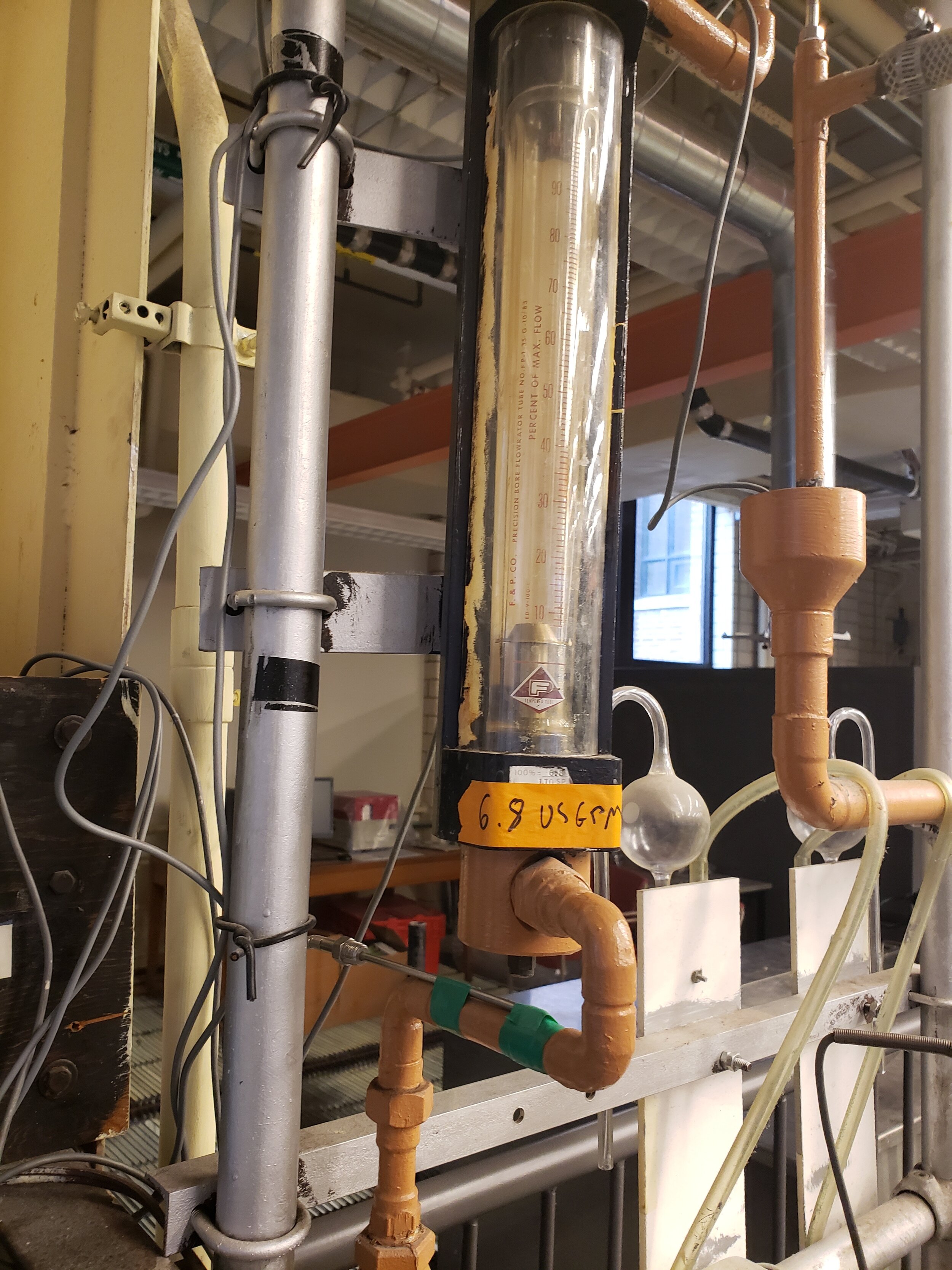
Adjust the condenser flowrate (with FIC-703) to ~15%.
4. Check if the lab TAs/supervisors drained steam line condensate (HV-805).
-
If not, wait for the lab TAs/supervisors to do so.
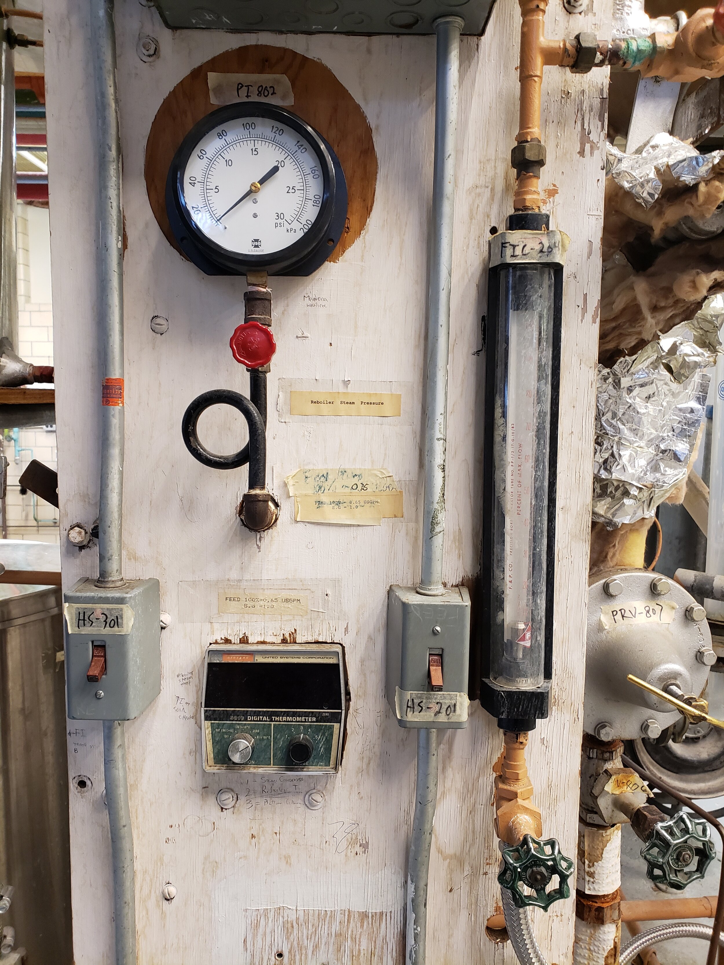
5. Introduce steam to the reboiler. Note: If you hear steam hammer, close HV-806/PRV-807 and go to step 4.
-
Slightly open the reboiler steam isolation valve (HV-806) (1-2 turns).
-
Control the reboiler steam pressure by slightly opening PRV-807 (turn clockwise).
-
Continue to open the PRV until desired operating reboiler pressure is met (5-15 psi shown on PI-802) and ensure that all the residual condensed steam is purged from the reboiler steam line.
-
If the PRV was fully opened to reach target pressure, close the valve with one 180° turn. DO NOT EXCEED 15 PSIG.
6. Introduce cooling water to the bottoms and product tanks by opening valves (HV-705 & HV-704), respectively. Open valves completely to avoid leaking.