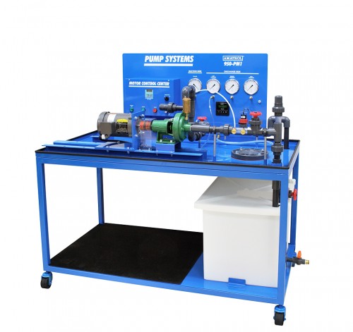
A pump is a mass transfer device that moves fluids by mechanical action from one location to another.
PUMP TERMINOLOGY
- Cavitation: The presence of vapor and or air pockets in and around the impeller of a pump when in use. This can be caused by the property of the solution, pump starvation and impeller speed. The radical changes of the fluid density in this region negatively impacts flow measurements and impeller wear and tear.
- Dead Head: All the flow from the discharge end of a pump is at a stand still. This can be accomplished by closing the output valve or by allowing the output head to max out.
- Flooded Suction: A pumping arrangement whereby the inlet fluid head is above the center line of the pump and thus by design no priming is necessary.
- NPSH: Net Positive Suction Head.
- NPSHA: Net Positive Suction Head Available. This is the actual fluid head at the suction end of a pump. It will include any loss due to friction and vapour pressure head loss.
- NPSHR: Net Positive Suction Head Required. This is the minimum fluid head required to prevent cavitation.
- Pump Curve: a graph that represents a pump’s flow capacity for a given head, or resistance to flow.
- Efficiency Curve: the ratio of the energy provided by the pump to the energy input by the motor to the pump shaft.
The following pumping arrangement illustrates the term ‘head’ as it applies to pumps.

Figure 2a: Pumping Arrangement-suction head

Figure 2b: Pumping Arrangement-suction lift
Pump Classifications
Pumps can generally be classified as being Dynamic or Displacement.
CENTRIFUGAL PUMPS
Centrifugal pumps are by far the most common type of pumps found in chemical industries. The reasons are:
- very versatile
- relatively cheap
- easy to maintain
- easy to install
- very forgiving.
Typical features:
- 90° arrangement-axial inlet, radial outlet
- characteristically curved impeller design
- significant gap (tolerance) between impeller and casing
- pump can be made of a single material or a combination of materials. Examples of materials used in making pumps are plastic, metal, rubber lined, glass lined.

Figure 3: Pumping Arrangement
OPERATING PRINCIPLE:
Liquid enters the pump inlet i.e., eye of the impeller, gets energized by virtue of centrifugal impeller action and is then discharged via the pump outlet. The energy imparted upon the liquid is a direct result of the impeller action which is then translated into an increase in velocity.
Note that:
a) with a centrifugal pump the outlet can be briefly closed while the pump is running and no damage to the pump will result,
b) depending upon the pumping arrangement a check valve must be installed to prevent siphoning,
c) no pressure relief valve is necessary to protect the pump and piping system,
d) as shown in figure 3b, the float, i.e., output rate is dependent upon the head in tank A. A displacement pump on the other hand will give a constant rate of output regardless of the head in tank A. The following graphs show centrifugal pump characteristic curves:

Figure 4a: Pump Curve Figure 4b: System Curve

Figure 4c: Pump and System Combined Figure 4d: Efficiency Curve

Figure 4e: Pump, System and Efficiency Combined Figure 4f: Impeller Curves

Pump Curves:
4a. Pump head capacity curve: Is a plot of various flow rates or capacity vs head unique to the pump
4b. System curve: Is a plot of capacity and head required for the various conditions of the system
4c. Plot showing the combined system and pump curve, the point of intersection is the point at which you operate the pump for your system
4d. Efficiency curve: A curve showing the ratio of work input to the fluid to the power supplied to the shaft
4e. Combined plot showing the ideal operating point at the intersection of the three lines 4f. Impeller curves: shows various flow rates and heads for different diameters of
impellers.
4g. Plot showing all curves combined. Intersection of all the curves produces the operating point for the pump and the shut-off head. This curve also describes the frictional losses in the system and the total static head.
PUMPS IN SERIES AND PARALLEL
What happens if your project calls for a tremendously large pump?
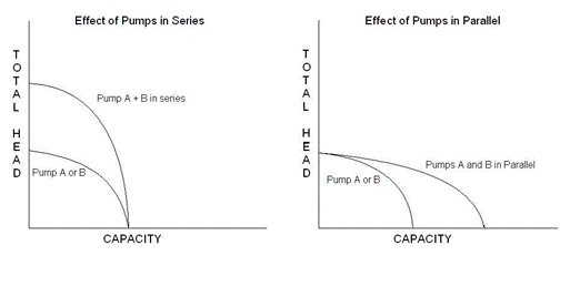
Figure 5a: Two pumps in series Figure 5b: Two pumps in parallel
Displacement Pump
So named because the pumping fluid is actually displaced, these pumps work by trapping a given volume of liquid between the gears, vanes, cylinders, screws or diaphragm and then forcing this trapped liquid through the pumps output. This on the liquid is translated to an increase in pressure at the discharged end. The pressure build- up can become dangerously high, therefore these types of pumps are normally installed with bypass systems and pressure relief valves. In their absence a displacement pump in operation can lead to either the pipe rupturing or pump burning out.
Examples of displacement pumps and typical areas of usage:
- diaphragm pumps – constant flow, high pressure
- screw pump – slurry mixture, constant flow
- peristaltic pump – constant flow, accurate flow
- piston and plunger pump – very high pressures