Equipment Description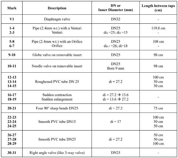
This whole lab is conducted on one unit. The unit is simply many different fitting and connections with multiple pipes in a circuit. You will be able to close certain valves to manipulate the flow of material to study different fittings and connections. The feed tank in this system is also just the collecting tank. In other words, the fluid in this whole system is simply recycled fluid that has already gone around the whole circuit. This allows for easy operation and fair testing. The description of the elements you will be studying is summarized below:
Background & Theory
To review concepts behind the leaching process, click here.
Virtual tour of the operation unit
ZOOM IN AND OUT TO SEE THE CLOSER LOOK OF THE OPERATION UNIT. YOU CAN ALSO SELECT ANY OF THE FOLLOWING CLOSE-UP TOUR TO SEE VALVES AND MEASUREMENT DEVICES ON THE UNIT.
2D P&ID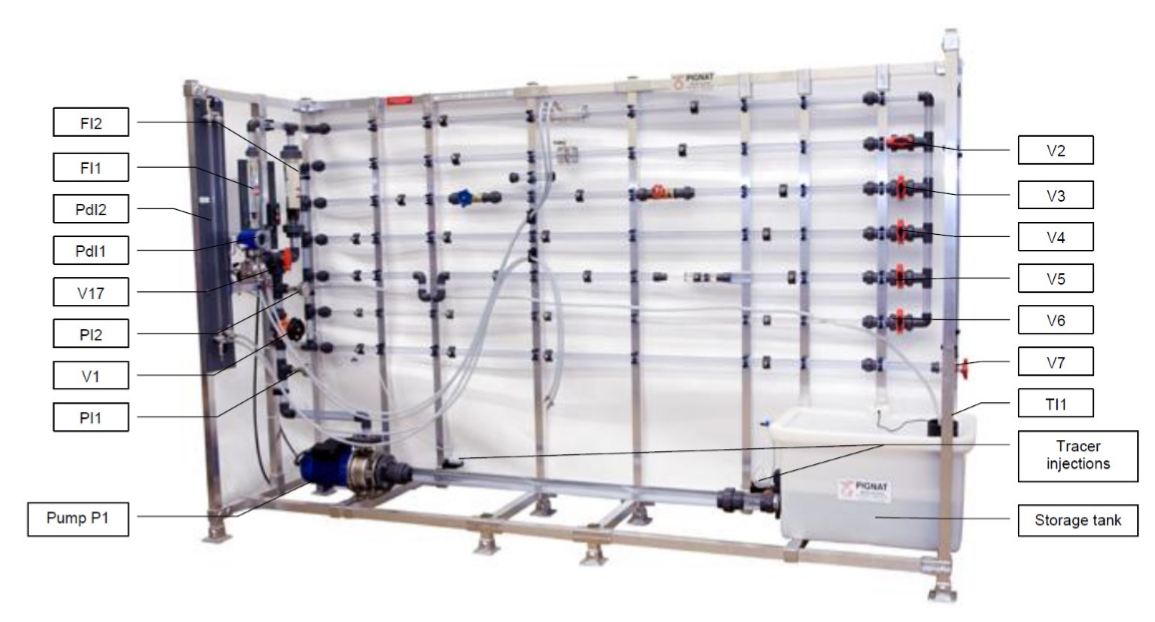
Click the image to download the SOP.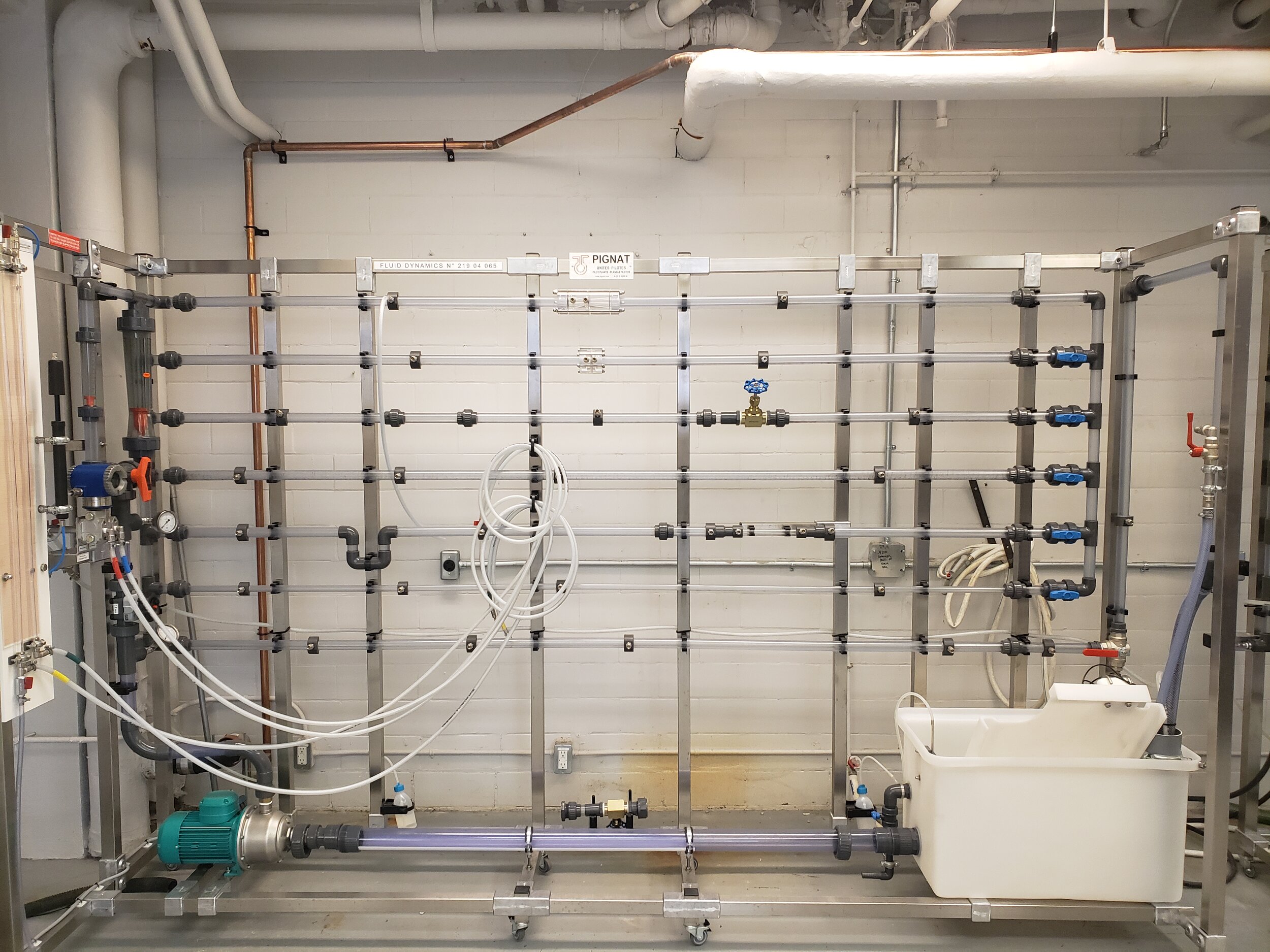


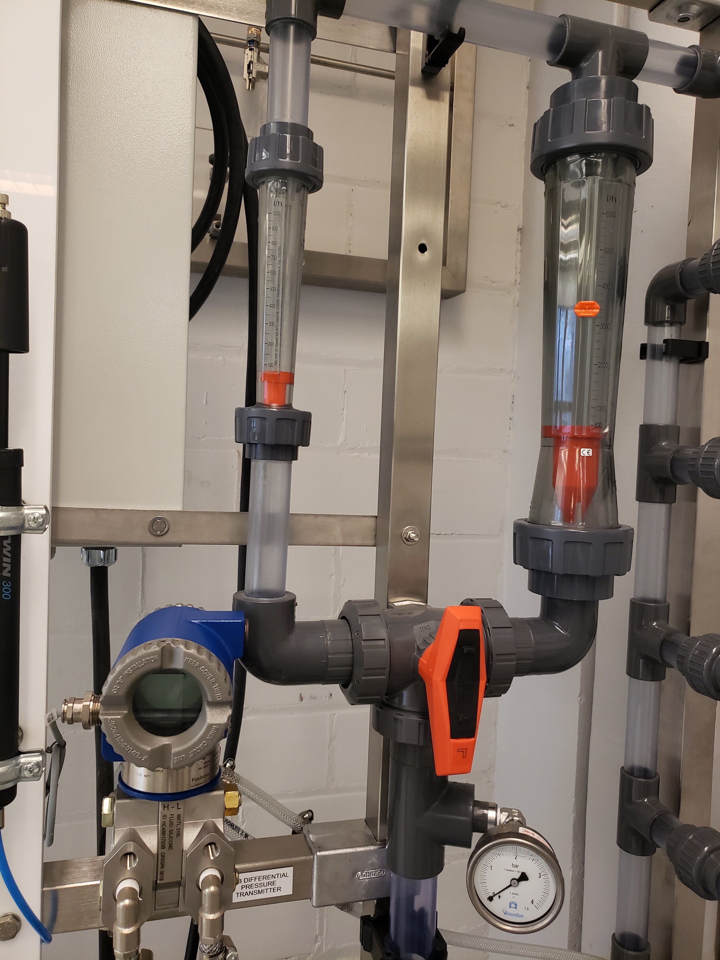
Measurement Devices Gallery
STANDARD OPERATING PROCEDURE
Startup Checklist:
-
Check that all the valves should be closed
-
Check that the unit is empty and clean
-
Pump is off and unplugged
-
Feed tank is filled to at least 70L in volume
-
Purge all the air from the system
-
Check the lab manual for detailed instructions (will be explained by the TA during the lab day as well – but come prepared for questions!)
-
Procedure:
The procedure essentially consists of creating different circuits to measure the pressure drop and flow rate across different fittings. Here, we will detail how to create the different type of circuits, how to switch between them, and how to use the pressure drop measurement devices. The float flow rate measurement devices can just be directly read from the equipment to retrieve that specific data point.
Creating your circuits:
-
Open V1 slightly (one turn)
-
Turn V17 so that it forces the flow to go through the flow meter F11
-
Here is where we can create the different circuits. Open the following valves to select the equipment to study:
-
V2 – Diaphragm
-
V3 – Valves (of different types)
-
V4 – Rough pipe (DN25)
-
V5 – Irregularities (minor loss equipment) like elbows, Tees, Unions, etc.
-
V6 – Smooth pipe
-
-
Turn V7 so that it forces the flow upwards
As you can see, the procedure for this lab is actually quite simple. Nothing more than turning some valves and adjusting flow rates and taking measurements. However, you should realize the there is a lot of data that will need to be recorded. You should make sure you come to this lab with a procedure and plan already in mind. Tables to record data should already be in your lab notebook to ensure you will not be missing data for your analysis.
Using the Pump & Adjusting Flowrate:
Once your circuits have been made, we can now operate the pump to perform the experiment.
-
Plug the pump into the nearest outlet and turn on the pump
-
The flow rate can be adjusted using V1
-
Position V12 to use F12 as flow increases
-
Turn off the pump to stop flow – Do not close V1 to stop flow!
Using Pressure Measurement Devices:
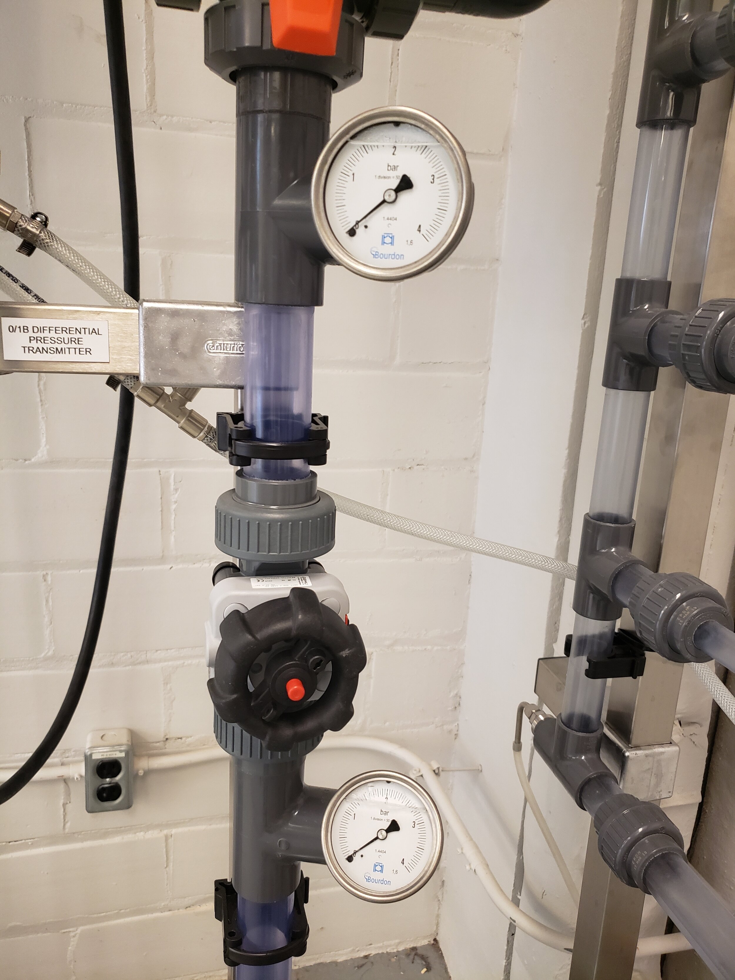
Differential Pressure Transmitter (PdI1):
This device is the simplest to use. Simply connect the high pressure hose (H) to upstream of the unit, and the low pressure hose (L). If the result is negative, simply switch the hoses.
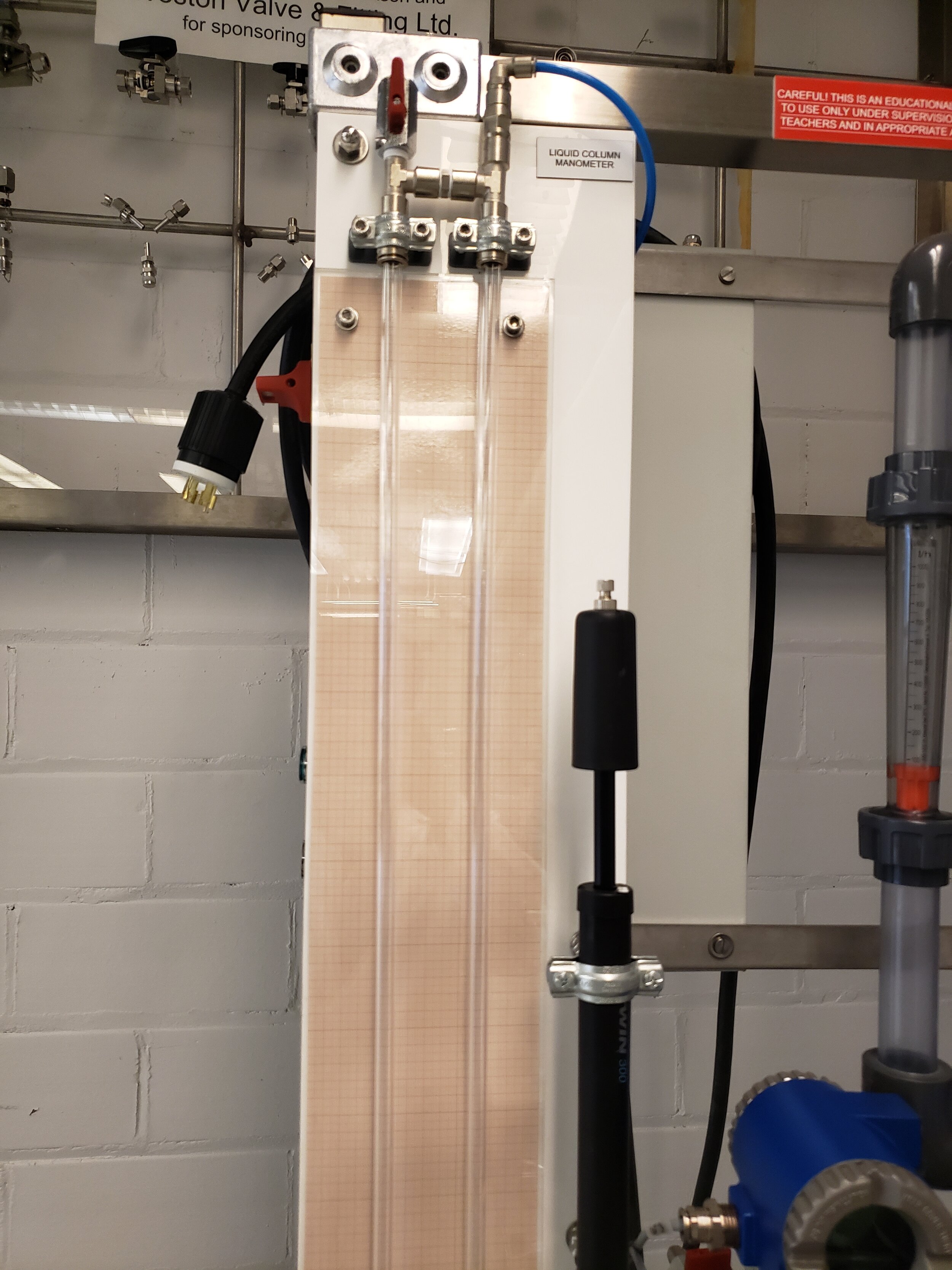
U-tube manometer (PdI2):
This device is just as simple to use, but there is a final conversion that is needed to calculate the pressure drop. Connect the hoses around the element you wish to examine, and record the height difference between the two sides. Using the fluid density, you can convert this height difference to a pressure drop.
Shutdown:
Empty the piping:
-
Turn off the pump and unplug it
-
Open valves V1 – V6
-
Position V7 to force the flow downwards
-
Connect the venting hose at the top of piping unit
-
Allowing air to flow in the system, wait until all the water in system flows out into a tank
-
Repeat step 5 for all elements in the unit until all the water is drained out
Empty PdI1:
-
Connect the hoses to position 2 and 3 (top of the unit)
-
Connect the venting hose to position 1
-
Open valves V13 and V14
Empty PdI2:
-
Connect the hoses to position 26 and 27
-
Position V7 to flow downwards
-
Close V15 and V16
-
Using pump P2, remove the water from the tubes and the hoses to the tank
-
Place a beaker under the drain valve V16
-
Open V15 and V16 to drain remaining water
Shutdown Checklist
-
Pump is off and unplugged
-
All valves are closed
-
There is no water in the unit