Equipment Description
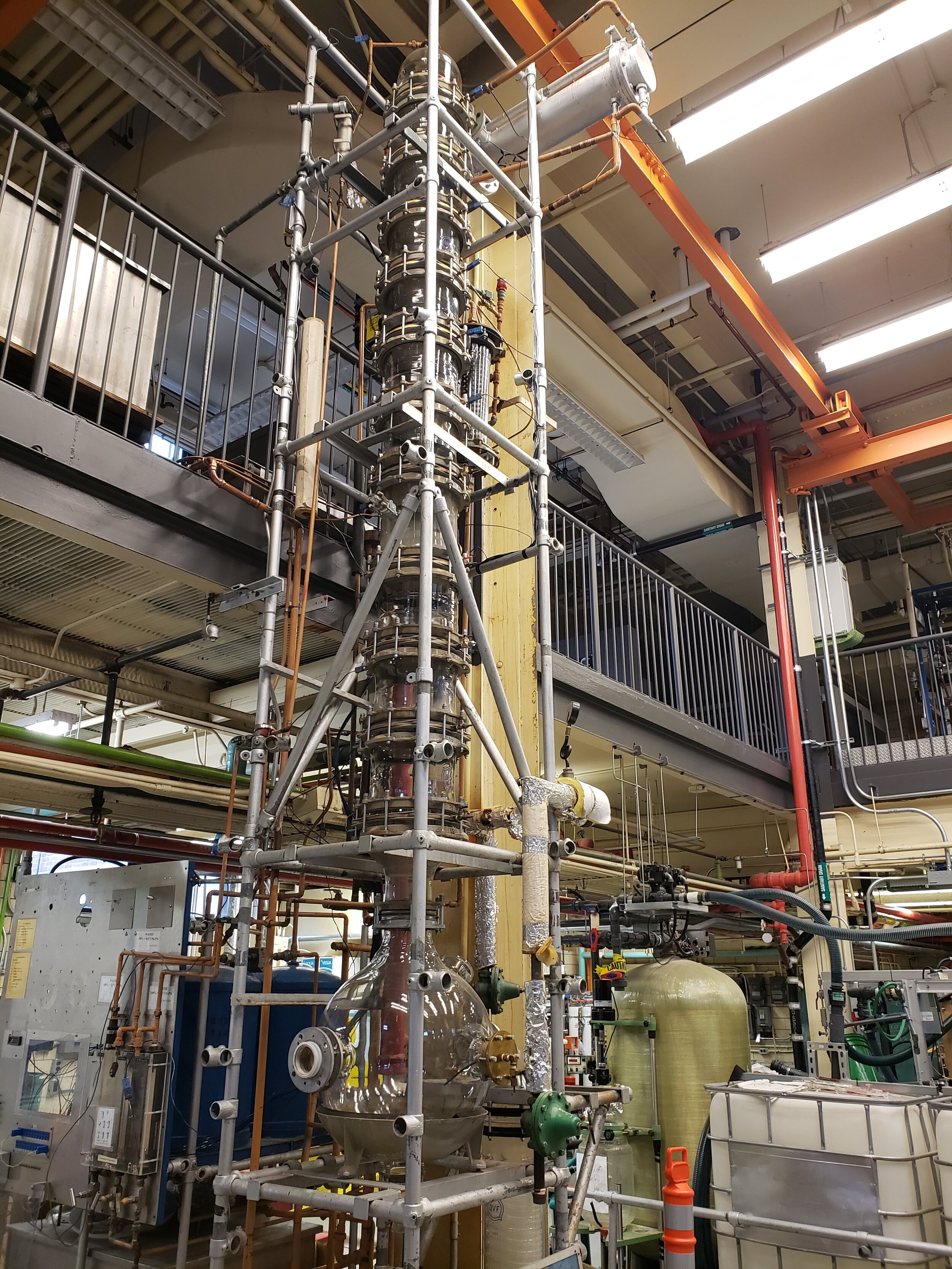
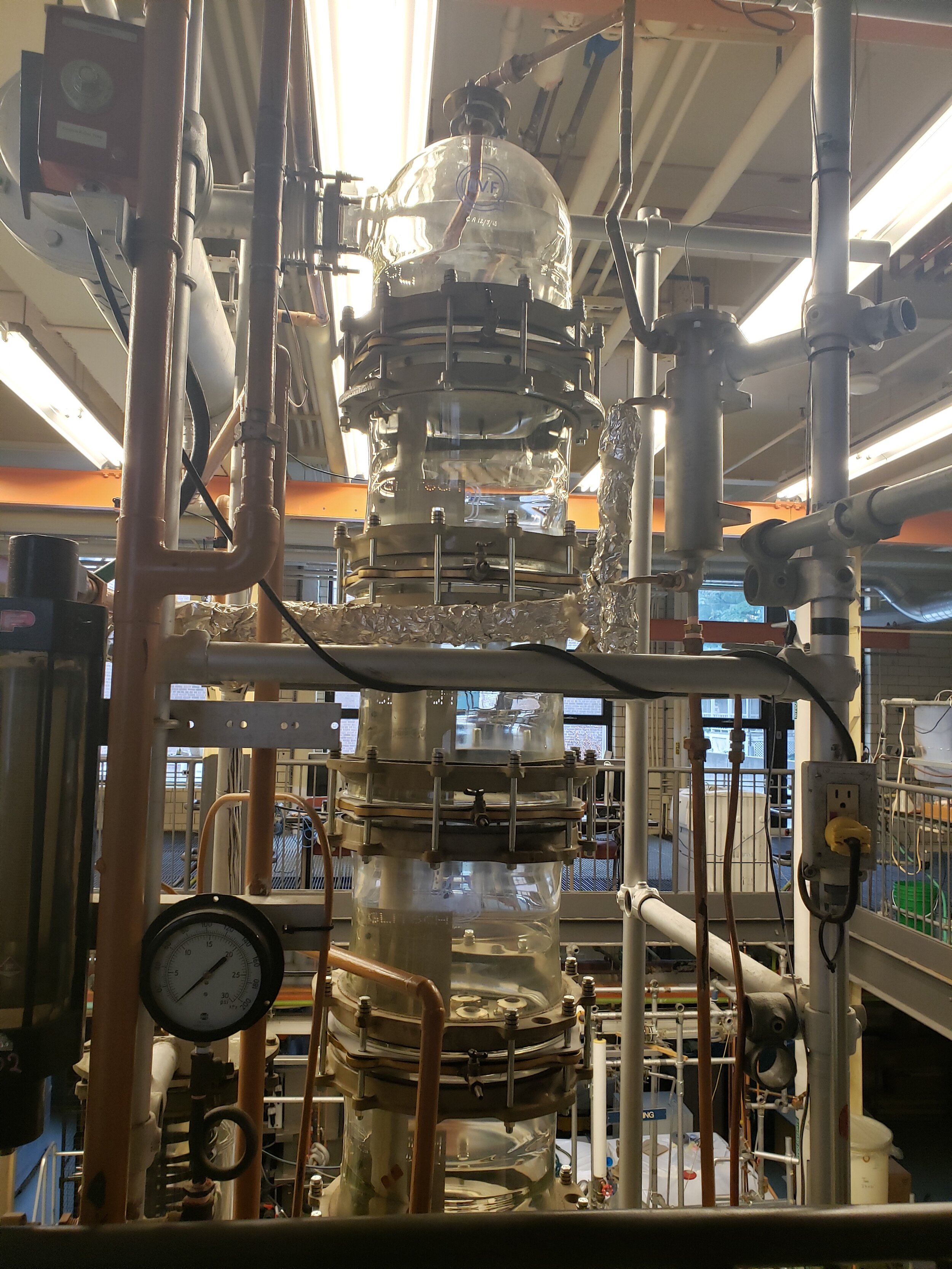
The plate distillation column stands at a height of __ and a diameter of 11.87 inches. There are 12 plates in the column where, from the bottom-up, there are 4 sieve trays, 4 ballast trays, and 4 bubble-cap trays. A pump is used to feed the streams into the column and there are pumps at the condenser and reboiler (to overcome head loss). We assume that the condenser is a total condenser and that the reboiler is total reboiler.
The sieve trays are sieve 57, where the hole diameter is 5mm. The ballast tray is ballast number 5 with a leg length of 0.313 inches. Finally, the bubble cap trays bubble cap number 5 with a skirt height of 0.5 inches and a cap diameter of 3 inches. The feed enters the column at plate 6.
Background & Theory
To review concepts behind the leaching process, click here.
Virtual tour of the operation unit
ZOOM IN AND OUT TO SEE THE CLOSER LOOK OF THE OPERATION UNIT. YOU CAN ALSO SELECT ANY OF THE FOLLOWING CLOSE-UP TOUR TO SEE VALVES AND MEASUREMENT DEVICES ON THE UNIT.
Piping and Instrumentation Diagram
ON A MOBILE DEVICE USE TWO FINGERS TO PAN, AND ONE FINGER TO ROTATE. ON A COMPUTER USE LEFT CLICK TO ROTATE, AND HOLD RIGHT CLICK TO PAN
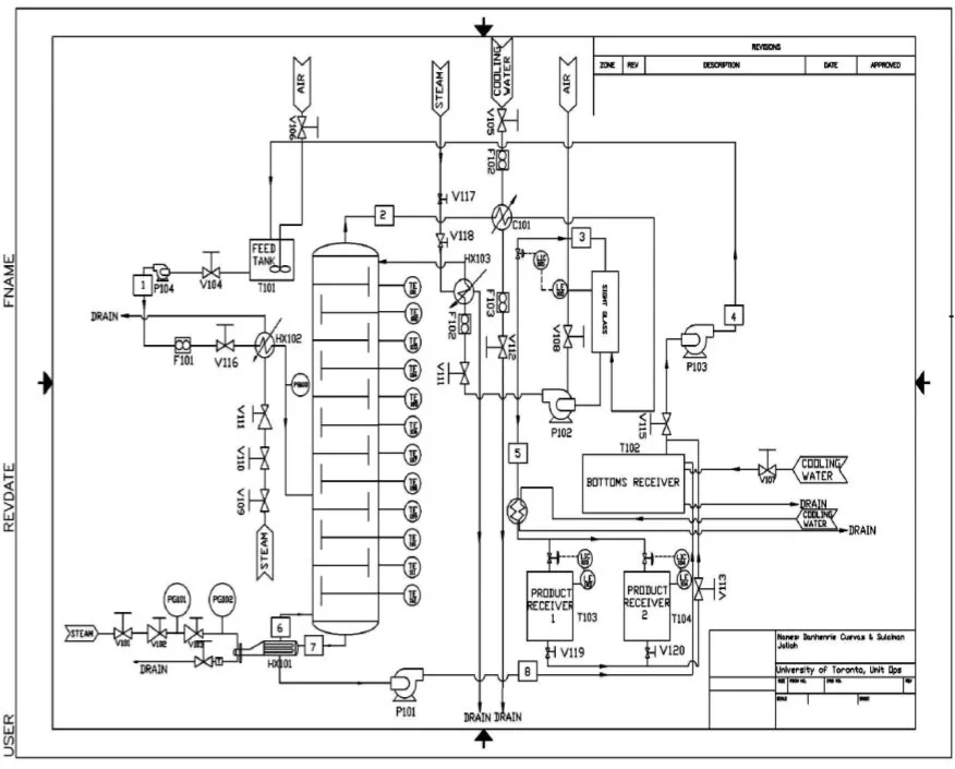
Click the image to download the SOP. The key for the P&ID is found in the SOP.
Gallery
STANDARD OPERATION PROCEDURE
Startup Checklist
-
The bottom level indicator (LE102) is at its lowest (bottom tank is empty)
-
V101 is closed
-
V103 is first closed, then V102 is preset to 15 psig overall steam pressure
-
PG101 is reading 0 psig
-
The condenser flow meter, F102, is 0% (located at the top of the column – upstairs)
-
The feed tank stirrer valve, V106, is at an ‘off’ position (closed)
-
Feed preheater, HX102, is off by checking that V107, V110, V111 are in a ‘close’ position
-
V107 is in a ‘closed’ position
-
All pumps (P101, P102, P103, P104) are turned off
-
Computer is on and ready to record data
Startup Procedure
-
Set all PL electrical breaker ‘on’
-
Set liquid level in the flask to a desired level
-
If not at the desired level, open V104 and open feed flow until at desired level
-
 Figure 1: Bottom tank at desired level
 Figure 2: Valve 104 (left) and feed flow meter 101 (right)
 Figure 3: Valve 103 for controlling steam in reboiler
4. Introduce steam in to the system VERY SLOWLY by opening V101 located on the right of the distillation column
Note: V102 is preset. DO NOT TRY TO OPEN OR CLOSE IT.
 Figure 4: Valve 101
5. Repeat step 3 until V101 is fully open. Turn the steam valve clockwise by 180 degrees. It will take approximately two minutes to see the condensate moving in the reboiler (HX101) resulting to 15psig pressure.
 Figure 5: reboiler for plate column
6. Adjust the PRV in front of the flask in increments of a notch every 30 seconds or so to fully introduce steam into the plate column. DO NOT EXCEED 10PSIG!
7. Repeat step 5 until all the condensate is safely purged out of the reboiler
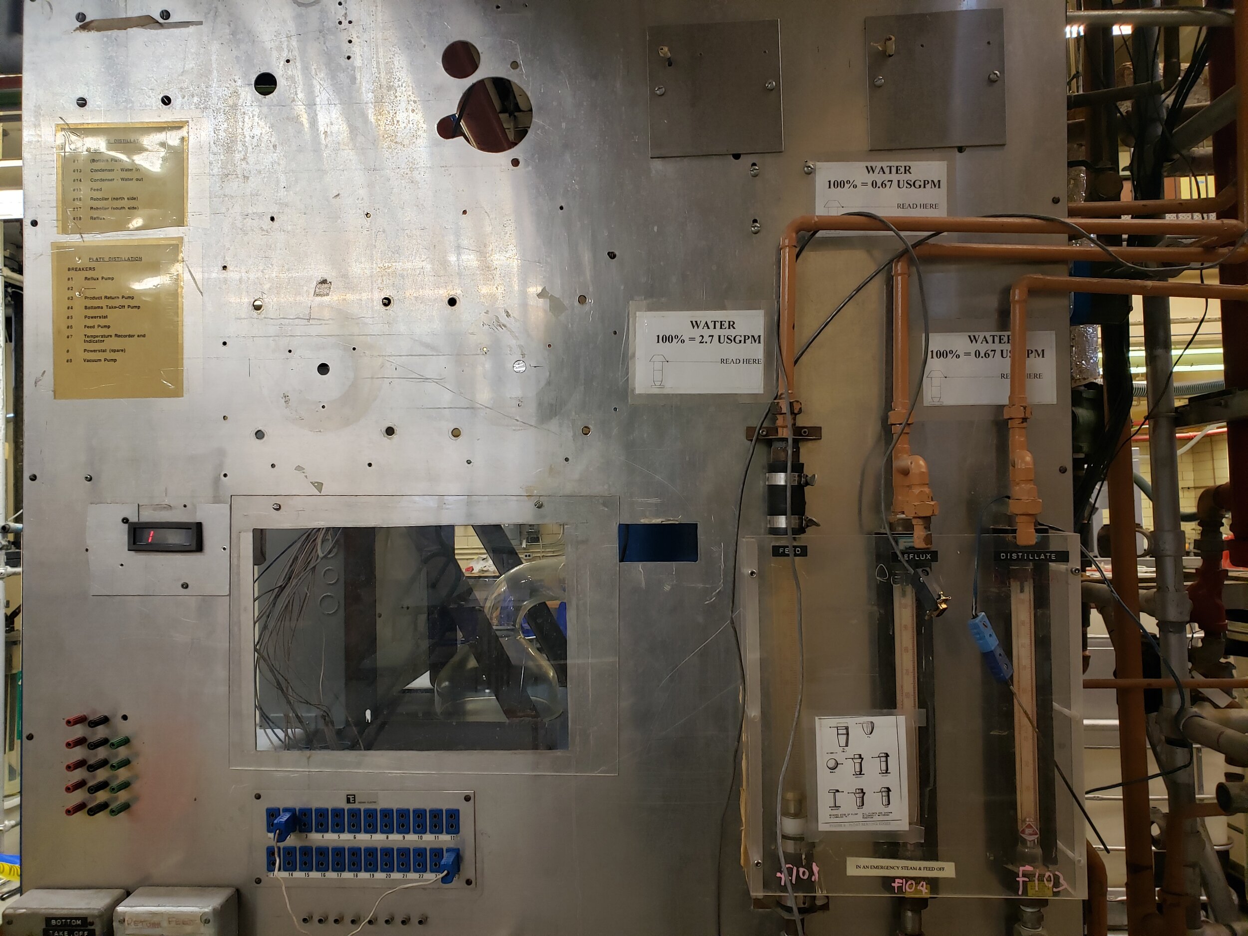
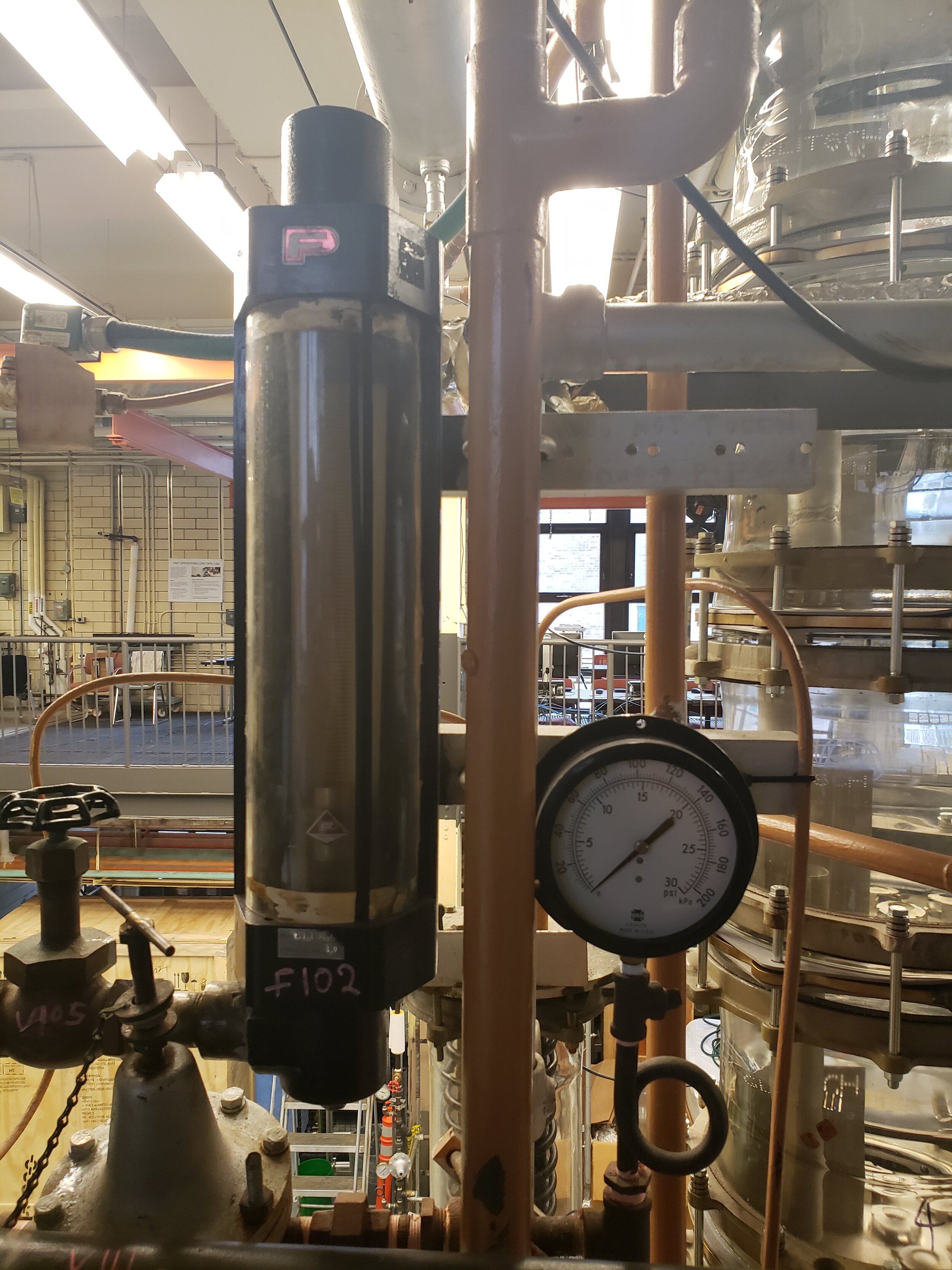
8. Adjust the condenser flow rate meter F102 to 15% using V105 (located upstairs)
 Figure 6: V105 and F102 for the top condenser
9. Adjust the air valve V106 to turn on the stirrer feed tank, T101, located at the top of the column
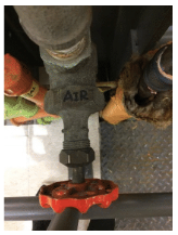 Figure 7: Air valve V106
10. Turn on the coolant valve, V107, for the bottoms tank, T102, located behind the distillation column
 Figure 8: Valve V107
11. When the mixture in the reboiler starts to boil, increase the condenser flowrate to 40%
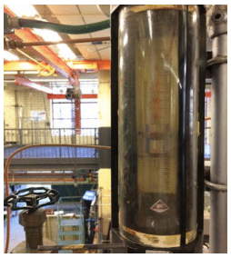 Figure 9: Flow meter F101
12. When the sight glass is 80% full, turn on the pneumatic pump, P102, by turning V108 open. Then turn on the reflux flow meter F104 to adjust level if needed
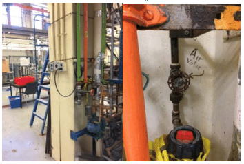 Figure 10. Air valve, V108, for the reflux pump, P102, located behind the vertical I-beam
13. Make sure the sight glass is maintained at 80% by adjusting the reflux flow meter, F104
14. Allow the column to run for at least 30 minutes while monitoring both the temperature profile using the computer, liquid level in the flask, and sight glass level
15. Once the system reaches steady state (temperature profile, pressure of reboiler, level insight glass and reboiler are steady) it is time to take samples
Recording Data
-
Start computer and click on the user “PlatestillUser”. Click on program ‘Plate still datalogger’, open a new file and save under “Plate” drive. Then proceed to hit on run/start to collect data.
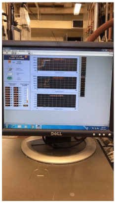 Figure 11: Desktop found upstairs next to the top of the packed column
2. Turn on water bath and calibrate temperature to 25 degrees Celsius by changing the temperature setpoint using the controls shown in Figure 14
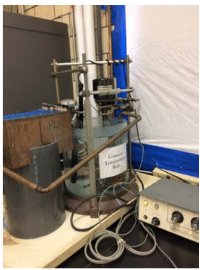 Figure 12: Overall setup for water bath
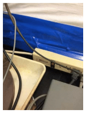 Figure 13: Power switch for water bath
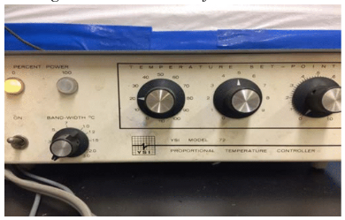 Figure 14 : Controls to adjust water bath temperature to 25 degrees
3. For sampling, have test tube racks, corks for test tubes and test tubes for each plate,bottom flask, condenser, and feed (15 in total). There are sampling ports for each plate and students must use insulated gloves when taking samples. Fill ⅔ of the test tube and cap it immediately
4. Place samples into the water bath for about 15 minutes
 Figure 15: Samples in water bath
5. Turn on density meter. Prepare to have a waste beaker
6. Once 15 minutes has passed, take samples to density meter and use plunger to analyze the sample. Let the density measurement stabilize and make sure there are no air bubbles in the ‘U’ tube
7. Use chart of physical properties for ethanol are provided to convert density to mass fraction
8. Once analysis is done, empty test tube samples into the waste beaker and dump into the feed tank
9. Repeat steps 3 to 8 when sampling more than one set of test tubes
Operating at Partial Reflux
-
Turn on the feed Pump, P104
-
Increase feed flow meter, F101 to switch to partial reflux condition
-
Adjust the reflux flow meter F104 and distillate flow meter to have a ratio of 2:1
Preheating the Feed
4. Adjust valve V109 to open the feed preheater, HX102
 Figure 16: Steam valve V109 for the preheater of feed located upstairs
5. Open V110 to halfway of the valve position
 Figure 17: Control valve V110 for preheater of feed located upstairs
6. Open V111 to 1 psig pressure
 Figure 18: Pressure Reducing Valve V111 for the feed preheater located upstair
7. Adjust the pressure reducing valve for the desired temperature. The temperature of the feed can be obtained from the digital reading for the feed plate (15) behind the column (for a reflux ratio of 2:1, the desired temperature is around 90~95°C)
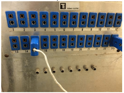 Figure 19: Panel used to record temperature of each plate
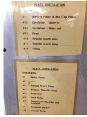 Figure 20: Legend of panel
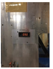 Figure 21: Temperature display
Shutdown Procedure
Shutdown of Steam to Reboiler
-
Turn off steam to reboilers by closing V101
-
Once pressure gauge PG 103 reading is down to zero psi, close V103 located in front ofthe flask at the bottom
Feed Preheater Shutdown
3. Turn off feed preheater HX102 by closing V109 located upstairs.
4. Close V110 completely located upstairs
5. Completely close V111 by turning the valve counter clockwise and check if steam is offby reading PG103
Condenser Shutdown
6. Turn down the condenser, C101 flow rate level to 25%
7. Turn off HX101-reflux preheater if it was turned ‘on’
8. Turn off P104 by having ‘Feed’ switch to ‘off’position
9. Turn off P102 by closing valve V108
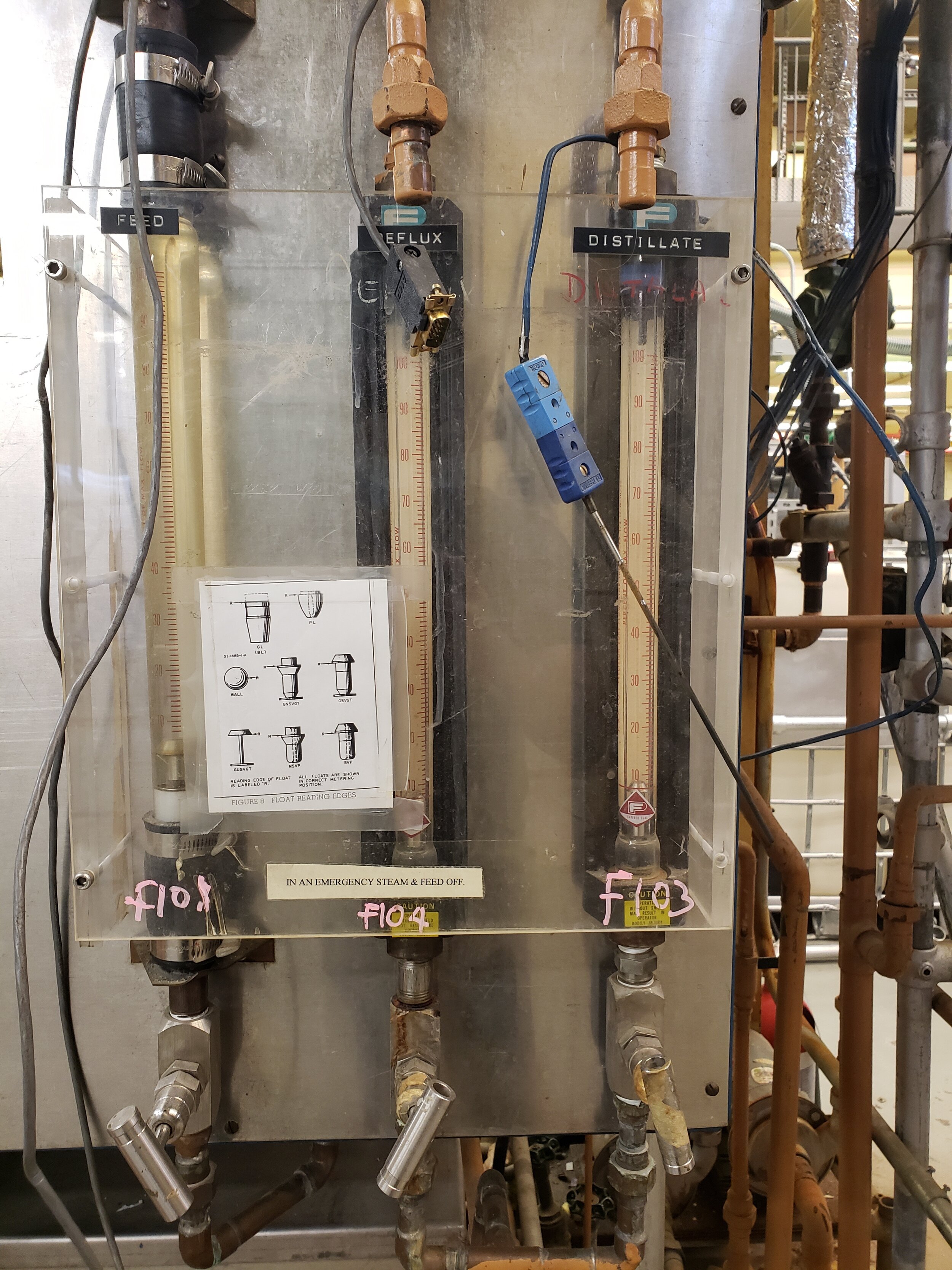
10. Close the F101, F102 and F103
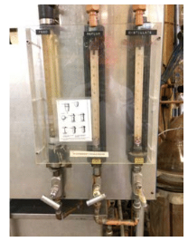 Figure 22: Feed (F101), Reflux (F102) and Distillate (F103) flow meters
11. Open product line valve V113 to get all distillate into the bottoms tank T102. Close once drainage is complete
12. Open V114 upstairs followed V115 downstairs and then start P102
13. After pumping up the bottoms and product to feed tank, close the valves you open for each case and then turn off the return pump
14. Clean all used test tubes for sampling and return back to PLATE locker
15. Save data and keep for analysis and report writing on a hard drive
16. Turn off computer by closing the program first and shutting it down
17. Turn off density meters after all samples have been analysed
18. Turn off the electrical water bath
19. Report back to your TA and make sure all checklist have been adhered to for shutdown before leaving the lab area
Shutdown Checklist
-
Valves V101, V102, V103, V110, V111,V117, V118 are closed
-
Valves V104, V106, V108, V112, V113, V115, V119, V120 are closed
-
PG101, PG102, PG103 and PG104 are reading zero
-
T102 is empty
-
All pumps are off: P101, P102, P103 and P104
-
All flow meters off: F101, F102, F103 and F104
-
If not, close valves V105, V111, V112, V116
-
-
Feed stirrer is turned off
-
If not, close valve V105
-
-
Water flow rate for the condenser C101 is at 25% and inform TA
-
Density meters are off
-
Water bath is off
-
Computer is off