Mathematical Discussion of Heat Exchangers
This section is dedicated to explain how to use certain mathematical functions are used to evaluate parameters involved in the design of a heat exchanger.
The main parameter we would like to evaluate for our system is the UA value. This value essentially is the coefficient to indicate how much energy is transferred to the fluid of interest depending on the temperature difference. The equation showing this relationship:
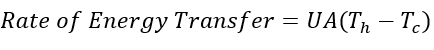
The subscript h indicates the temperature of the heating fluid and subscript c indicates the temperature of the fluid of interest (feed stream). The energy transferred will be a positive number, indicating that the heat is flowing from the heating fluid to the feed stream.
But how do we evaluate UA? From the SOP, which indicates the specifications of the heat exchanger, we know what the area at which the heat flows through. So now the question becomes how do we evaluate U? Generally, U is determined experimentally. This is what you’ll be doing in the lab. You will run the heat exchanger and record the data needed to determine U. This can be done using spreadsheet software to analyze the recorded data.
However, what if we want to design a heat exchanger? We can’t simply construct a potential design, run the experiment and determine the U value. This would not only incur a heavy cost on the designer and waste time, but also it might turn our design is not effective. Thankfully, researchers have developed empirical equations to effectively (and quite accurately) determine a theoretical value for U.
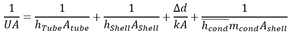
The equation we will use to determine U is as follows:
| Variable | Meaning |
|---|---|
| U | Overall heat coefficient |
| h | Heat transfer coefficient |
| A | Area (subscript indicates the area of interest) |
| k | Thermal conductivity of pipe |
| d | Thickness of pipe |
The factors involved here are generally ones to have the most effect on the overall heat coefficient. Now we have an equation that can calculate the value of U. All we need to do is calculate the heat transfer coefficients involved in the equation. Thankfully, engineers have developed empirical equations that can quite accurately estimate these values. To start our discussion, let’s begin by examining the tube-side heat transfer coefficient.
Tube-side and Shell-side Calculations
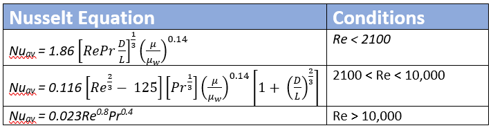
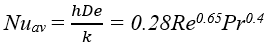
As we can see from the conditions of the Nusselt Equation table, we first must calculate the Reynold’s number of the tube-side and shell-side fluid. It is very important that you have this value. If you notice that the regions of the Reynold’s number (laminar, transition, turbulent) are specified here. As you probably know from your heat transfer course (CHE210), the type of flow for the fluid, where there is a transfer of heat, greatly affects the heat transfer coefficient between the two mediums.
The Nusselt number is a ratio of the convective heat transfer to the conduction heat transfer. The Nusselt Equations allow us to estimate this ratio so that we can then use it to calculate the convective heat transfer coefficient. On the tube-side and shell-side, the flowing fluid can essentially be treated as a bulk fluid, which allows to model the heat transfer of the tube-side and shell-side fluid as convective heat transfer. Even though there is conduction occurring in this fluid, you will notice the Nusselt values we will be working with will show that the ratio is heavily in favor of the convection rate. This allows to then assume that most of the heat transfer occurring on the tube-side and shell-side fluid is convective, and we justifiably neglect the conduction rate. This is why in the overall heat coefficient equation, we can ignore the conduction rate of both fluids.
It is worth noting the equations above are only work for a shell&tube heat exchanger. For a plate&frame heat exchanger, the Nusselt equation has the following form.
You will notice that rather than having three different equations, there is only one correlation for a plate and frame. Why is that? Think about the flow of the fluid in between the plates. Not only is it a small distance between the plates, but these heat exchangers are run at low-to-medium pressure.
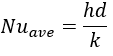
By rearranging this equation, we can then solve for h. It is worth noting that the variable “d” here is the hydraulic diameter. For a circular pipe, the hydraulic diameter is simply the diameter of the pipe. The “k” here is referring to the conductivity of the fluid, NOT of the material making up the pipe.
Steam condensate Consideration
So we have learned how to evaluate the first two terms to achieve the heat transfer coefficient on both sides of the tube. The third is simply the heat transfer through the material of the pipe – which is simply conduction through the pipe. But what about the 4th term? This term is referring to the condensate of the steam (heating fluid). Since the steam is providing the energy to heat to up our fed fluid, it is natural to assume that some of the steam might condense on the shell-side of the tube. This adds another layer of resistance for the heat transfer, which affects the overall heat coefficient.
Thankfully, Nusselt has developed another equation to estimate this heat transfer coefficient:
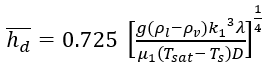
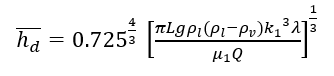
This equation can then be reduced to a simpler form:
Other Considerations
Large variances in inlet and outlet temperature
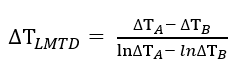
The equation at the top of the page does work when there is not too much variance between the temperature of the inlet and outlet. However, in this lab you might experience large variances, and if you checked the the theoretical U value, you’d notice that it does seem quite off the real (experimental) value.In this case, we need to use the log mean temperature difference (LMTD).
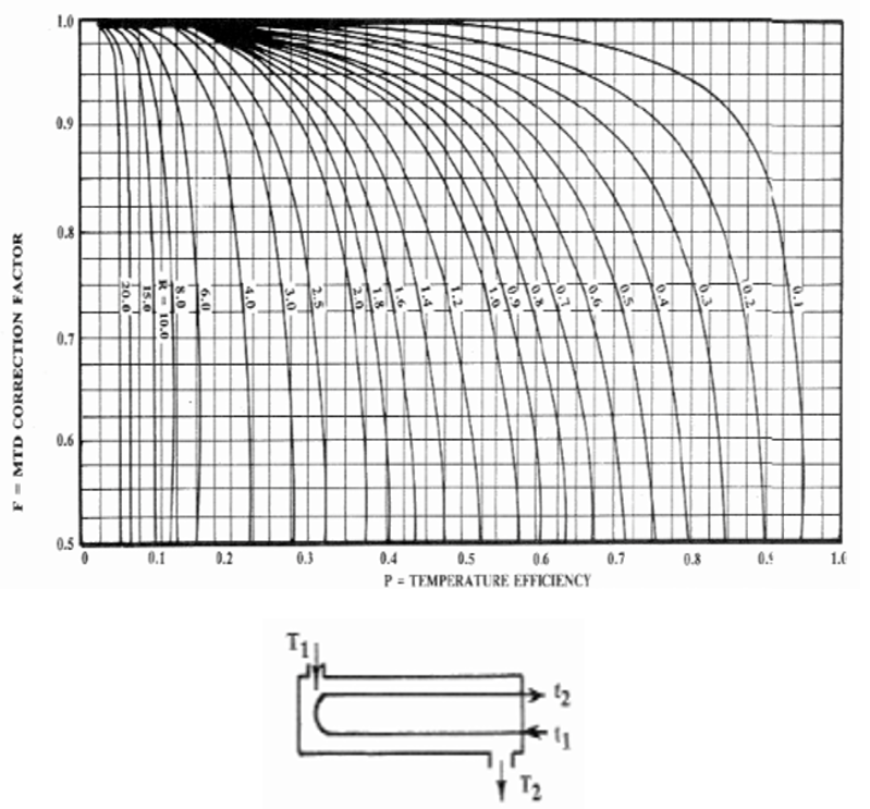
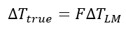
Non-perfect co-current or countercurrent flow
The equations we have been discussing thus far has one major assumption: the flow, whether co-current or countercurrent, is perfect. In reality, the flows in both mediums will be mixture of cocurrent and countercurrent. Correlation graphs do exist which will give you a correction factor so that you can capture the true temperature difference. As an example, we have provided one for most shell&tube heat exchangers:

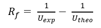
Fouling
You might still notice that your theoretical U-value is still a bit off. If you remember from our discussion, we were discussing the upkeep of a heat exchanger. One reason to do this is because of fouling. Fouling is essentially unwanted deposits of material on the inside or outside of pipe. This could simply arise because of the metal corroding. Fouling can be estimated from correlations developed by engineers but there is still some variation between the fouling you see experimentally compared to the theoretical fouling factor. This is just because there are many variable that can contribute to the extent of fouling in the system.
It is better to just determine how much fouling actually exists in the system already. This will give not only a more accurate value to the actual amount of fouling, but also let you determine how long it took to foul this much; set a limit for fouling before you might consider some down time for the heat exchanger to be cleaned, etc.