Heat Exchangers
Relevant Files for this unit:
Virtual Tour (Choose HX for now in the bottom left corner):
Introduction
The basic concept behind a heat exchanger is it allows for two fluid mediums (gas or liquid) to transfer heat between each other efficiently. This basic concept allows for our fluid of interest to be heated or cooled, which may be desired depending on the process conditions. For example, suppose you produce a product coming out of reactor at 500°C. We cannot collect the final product at such a high temperature for a multitude of reasons: thermal stability of the product (may break down at such a high temp. for a prolonged period of time); a purification process may be performed after collecting the product; the product needs to be cooled down for safety concerns, etc. Adding a heat exchanger unit coming out of the reactor is a simple solution as it can quickly cool down the product.
Types of Heat Exchangers
There are 3 different types of heat exchangers, each filling their own role:
-
Shell and Tube
-
Plate/fin
-
Boilers/Condensers
If you have any prior knowledge of heat exchangers, you might notice that there are definitely even MORE types of heat exchangers! Many more! Generally, most of these exchangers you may be thinking of are subsets of these 3 types. For example, a U-tube heat exchanger is essentially a redesign of the internals of a basic shell and tube heat exchanger. What differentiates each of these exchangers is how heat is transferred between two fluids. A more detailed discussion of a shell&tube and plate&frame can be found here.
To look at a mathematical discussion behind heat exchangers, click here.
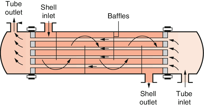
Photo taken from the following URL: https://www.researchgate.net/publication/308464270_Heat_Exchanger_Types_and_Classifications Photo taken from a publication by Bahman Zohuri in his paper “Heat Exchanger Types and Classifications”.
This exchanger consists of a shell, where the heating/cooling fluid flows through, and a tube , where the feed stream flows through.The internals of this heat exchanger can be redesigned to meet the design specifications of your process. Redesigning the internals may also help with the upkeep and costs that come along with having a heat exchanger.
For example, a straight shell and tube is the simplest design which can drastically cut the cost initially. However, if you anticipate a significant amount of thermal expansion, the design will be ineffective with the high upkeep costs. A U-tube design is more efficient at dealing with thermal expansion, which will overall decrease the cost in the long run.
2. Plate & Frame Heat Exchangers

Photo was taken from the following URL: https://www.ipieca.org/resources/energy-efficiency-solutions/efficient-use-of-heat/heat-exchangers/ Photo was adapted from an article (2014) from IPIECA.
This exchanger consists of metal plates fitted on a frame in series. The plates are welded on to the frame and using sealants to ensure there are no leaks in the system.
From the schematic, we can see that the heating fluid comes in at the top flows down in between two plates. The product stream comes in from the bottom flows up the exchanger in the next pocket between two plates. Heat is exchanged across the plate in between the two fluids due to the temperature difference.
The internals of this heat exchanger can be varied to a great degree (except by changing the area of the plates or number of plates) but the main advantage here is the simplicity in the upkeep. Replacing or adding new plates can easily be done with not much down-time. A more detailed discussion can be found by clicking the image.
3. Boilers/Condensers
This system can actually just consist of a plate & frame or a shell & tube heat exchanger. The reason this is specified as its own type of heat exchanger is because of the additional design considerations that have to be taken into account. The main difference here is that there will be a phase change for one, if not both, of the fluids. For example, if the a liquid is vaporized into a gas, the pressure in the vessel will begin to increase, which can damage the boiler if not considered. The enthalpy of vaporization also needs to be taken into account to ensure a quality design.
For the purposes of CHE304/305, you will not be dealing with this sort of system. However, many of you will be taking a design course in the fall or winter so this section is mainly supplementary information for your use in other courses.
Types of Flow
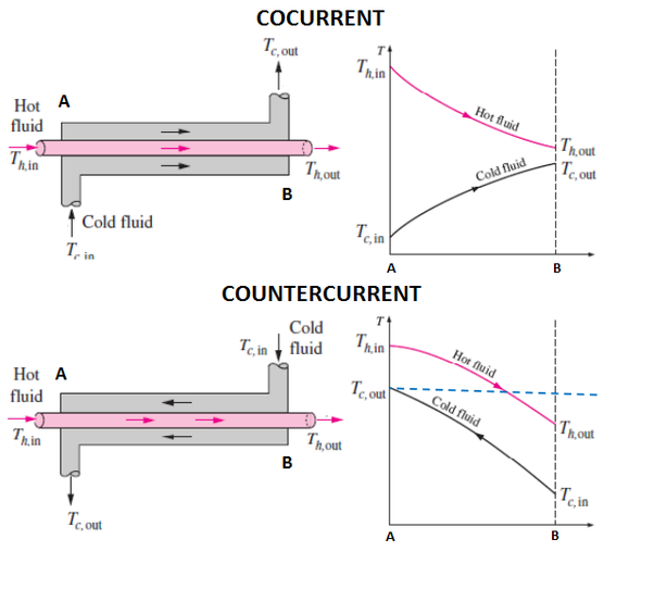
Now that we have looked at how each type of heat exchanger, we can look at the arrangement of the flow of fluids within the heat exchanger. There are two set ups for this:
-
Cocurrent flow
-
Countercurrent flow
As we can from the name, one set up is where the fluids are both flowing in the same direction (co-current) and the other is both fluids are flowing in opposite directions (countercurrent). To compare the two different arrangements, we apply the concept of log mean temperature difference (LMTD). The LMTD of a countercurrent flow arrangement shows to be much higher than in a cocurrent arrangement, which actually indicates a lower heat transfer area could be used for this system or less plates are needed in a plate&frame arrangement, which lowers the cost of the equipment (and upkeep cost). A cocurrent flow will need a larger area of heat transfer but does allow for a higher temperature gradient in the beginning, which if early heating is needed or beneficial, it may be worth considering a cocurrent arrangement.