Drag Concepts & Discussion
Introduction
An object will experience drag as long as the fluid has a viscosity (superfluids, fluids with zero viscosity, exist but are out of the scope of this discussion). What is viscosity? Formally, we can describe viscosity as a fluids resistance to deformation under shear stress. If this still seems pretty unclear, imagine the object flowing through the fluid. In solids, shear stress deforms due to the tangential force changing its shape. Liquids can freely change their shape as they have the ability to take up the shape of whatever container they are in. Shear stress in a fluid causes for fluid particles to flow at a different velocity than one another. This difference in velocity is the deformation we are interested in.
Forces Experienced (Buoyancy and Drag)
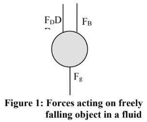
Three forces are always acting on our object. Its weight (Fg), buoyant force (Fb) and drag (Fd). Two of these forces are intrinsic to the system. The weight is depended on the mass of the object and the buoyant force is dependent on the volume of the object and the density of the fluid. Generally, these forces will not change throughout the objects flow since the dependent variables won’t change (unless there is a temperature gradient). So we would know that at steady state, the velocity of the object has reached terminal velocity and that the following relationship is true:
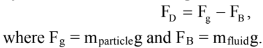
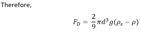
Try to see if you can prove the Fd equation from the relationship on the left!
Therefore, we can see that the steady state value of the drag force can be calculated from first principles. Two types of drag forces exist:
-
Viscous drag
-
Pressure drag
We have discussed how viscous drag arises (shear forces). Pressure drag arises due to an uneven distribution of pressure surrounding the surface of the object. How does this uneven distribution arise? The object moving through the fluid will compress the particles in front of it (in front of its direction of movement). As the fluid flows around the object, particles at the front are compressed together in a smaller volume, so therefore, by definition, since the fluid particles have been compressed, the pressure in front of the object is higher than it when it flows behind it. Depending on the speed and geometry of the object, the layers of fluid flowing behind the object may separate away. This will be further discussed below but this is what we call the point of separation.
Coefficient of Drag
Suppose that we would like to design a system where we would like for an object to flow through a fluid at some range of speeds. To design this a suitable pump for this system, we will need to estimate the drag an object may experience at different velocities. We define the coefficient of drag as follows:
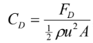

Using the coefficient of drag, we can determine the force an object will experience at any velocity. The area of typical shapes can easily be calculated. For example, in a spherical object, the projected area would simply be the area of the circle using the diameter of the sphere. Irregular objects, such as a jagged stone, is not as simple.
Before moving on with our discussion, we should first look at factors that can affect the drag an object experiences. Obviously, the type of fluid and the flow of the fluid will have an effect on the coefficient of drag. However, in this lab, we are mostly concerned at investigating how the geometry of an object can affect the drag. For example, we can see larger objects will experience more drag due to its projected area being larger than a small object. What about objects with sharp ends? Or objects that are “streamline”?
Correlation of Cd against the Reynold’s Number
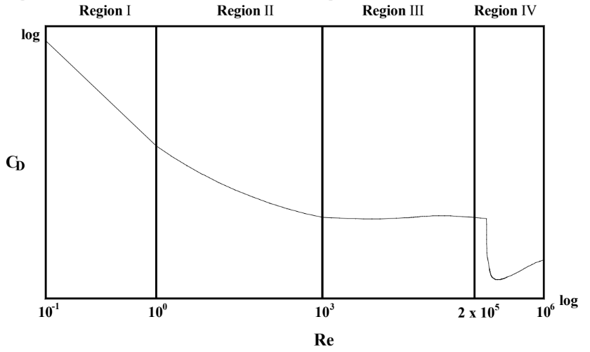
The correlation graph above has been determined for spherical objects. These correlations can be used to estimate the coefficient of drag for spherical objects. Since the geometry of an object can greatly affect the coefficient of drag, we cannot use these correlations for a cube without making some adjustments. Thankfully, we can adapt the shape of non-spherical objects to this graph by modelling it as a sphere with an equivalent diameter.

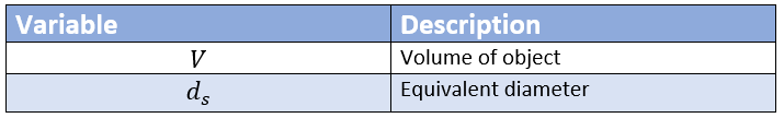
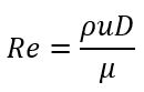
Using the equivalent diameter calculated from the equation above, we can now calculate the Reynold’s number and use it to estimate the coefficient of drag.

From the graph, we can see that there are 4 distinct regions where there are discontinuities in the graph. Each region can be modeled by different equations of approximation. A detailed discussion of each region can be found below:
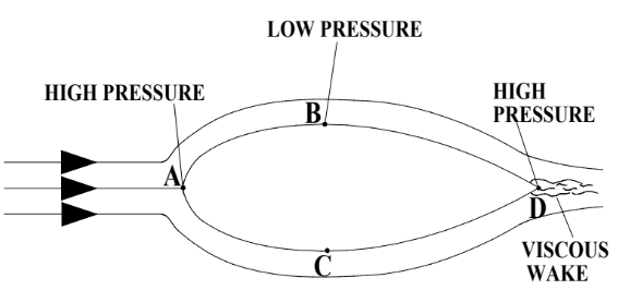
Streamlined Objects
The objective when streamlining objects to minimize the wake region by having the boundary layer exist for as long as possible. To do this, we must design an object that reduces the likelihood of a point of separation existing. The tapered end of the object causes for the pressure gradient from points B and C (minimal pressure) to point D is gentle. Since the flow of fluid particles from B and C to point D is against such a moderate pressure gradient, the particles do not separate. A very small and narrow wake region may form at the tip of tapered end, but this is such a small wake region that the pressure in front and behind the object is approximately the same. Due to the small wake region, streamlined objects will always experience less drag than blunt objects in similar environments.